Method for synchronously switching trigger timing of semiconductor valves

A synchronous switching, semiconductor technology, applied in the output power conversion device, electrical components and other directions, to achieve the effect of low hardware requirements, simple and easy switching method, and large scope of application

Active Publication Date: 2010-06-23
CHINA ELECTRIC POWER RES INST +1
View PDF1 Cites 19 Cited by
  • Summary
  • Abstract
  • Description
  • Claims
  • Application Information

AI Technical Summary

Problems solved by technology

[0008] (2) The trigger sequence proposed in the invention application 200610064919.2 is only applicable to the specific power electronic circuit of the overcurrent test device

Method used


Image

  • Method for synchronously switching trigger timing of semiconductor valves
  • Method for synchronously switching trigger timing of semiconductor valves
  • Method for synchronously switching trigger timing of semiconductor valves

Examples


Embodiment Construction

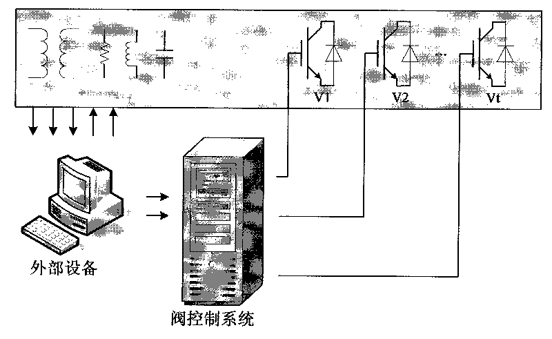
[0039] A typical large-scale power electronic device can be used figure 1 hint. Such devices usually include transformers, resistors, reactors, capacitors, semiconductor valves and corresponding control equipment. The control equipment can be divided into the valve control system specially used to trigger and shut off the semiconductor valve and the external automation equipment (referred to as external automation equipment) to complete other control and protection functions.

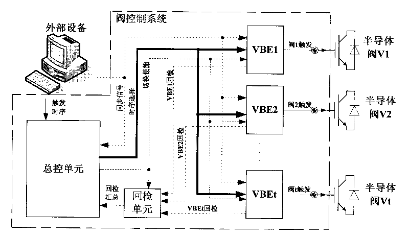
[0040] The schematic diagram of the valve control system of the present invention is as attached figure 2 shown. The system includes a master control unit, a checkback unit and a valve base electronic unit (VBE) of each semiconductor valve. The master control unit receives the "trigger timing" signal issued by the external automation equipment (external automation equipment for short), which can be any form of parallel or serial code, and is used to indicate the new trigger that each semiconductor v...


PUM


Abstract

The invention provides a system and a method for synchronously switching trigger timing of semiconductor valves, belonging to the field of power electronic automation. The method is realized through a set of valve control system. The valve control system comprises a master control unit, a return inspection unit and valve base electronic (VBE) units of valves. The master control unit is used to receive trigger timing switching order given by the outside and to adjust the entire timing switching process. Each VBE unit is used to verify the trigger timing selected by the master control unit and to feed back return information to the return inspection unit after check and to trigger or cut off the corresponding valve according to the selected trigger timing. The return inspection unit is used to receive the return information reported by each VBE unit and to feed back the information to the master control unit after the information is summarized. The method can satisfy the requirements of converter valve operation testing devices or other large-scale power electronic devices on the synchronous switching of valve trigger timing.

Description

technical field [0001] The invention belongs to the field of power electronics automation, and in particular relates to a method for synchronously switching valve trigger sequences in a converter valve operation test device. Background technique [0002] Large-scale power electronic devices are widely used in flexible alternating current transmission (FACTS), high voltage direct current transmission (HVDC) and other industrial fields. The main circuits of these power electronic devices all include a plurality of semiconductor valves of different types and in different quantities. These semiconductor valves are triggered and controlled by specialized automation equipment, valve control systems. The valve control system triggers or turns off these semiconductor valves (applicable to fully controlled devices such as IGBTs and MOSFETs) according to a specific time sequence, and this time sequence is usually called a trigger sequence. [0003] In order to realize some complex a...

Claims


Application Information

Patent Timeline
Patent Type & Authority Applications(China)
IPC IPC(8): H02M1/088
Inventor 张新刚查鲲鹏吕铮王韧秋姜喜瑞杨卫刚
Owner CHINA ELECTRIC POWER RES INST
Why Eureka
Try Eureka