Load transient change detecting circuit for voltage converter and application circuit thereof

A technology for voltage converters and load transients, applied in the direction of adjusting electrical variables, converting DC power input to DC power output, instruments, etc., can solve problems such as poor transient response and complex structure, and achieve wide application and simple structure Effect

Inactive Publication Date: 2010-06-23
CHENGDU MONOLITHIC POWER SYST
View PDF4 Cites 28 Cited by
  • Summary
  • Abstract
  • Description
  • Claims
  • Application Information

AI Technical Summary

Problems solved by technology

This method compares the compensation voltage of different clock cycles to obtain the transient change signal, which has a large hysteresis, and is limited by the limited rate of change of the compensation voltage, and the transient response is not good.
In addition, other transient change detection includes detecting the output current or output voltage, and judging the transient change by comparing the difference before and after a certain period of time. This method needs to have a detection sampling circuit and a judgment circuit at the same time, and the structure is relatively complicated.

Method used


Image

  • Load transient change detecting circuit for voltage converter and application circuit thereof
  • Load transient change detecting circuit for voltage converter and application circuit thereof
  • Load transient change detecting circuit for voltage converter and application circuit thereof

Examples


Embodiment Construction

[0042] Specific embodiments of the present invention will be described in detail below. It should be noted that the embodiments described here are for illustration only, and are not intended to limit the present invention.

[0043] Based on specification descriptions and considerations for easy reading, the terms appearing in the patent application documents of the present invention are defined one by one as follows: the voltage converter in the present invention is a DC-DC voltage drop converter (Buck) or other types of converters, such as Boost Transformers converter or Buck-Boost converter. The invention can be used to control single-phase voltage converters, and can also be used to control multi-phase voltage converters.

[0044] It should be noted that the above terms are only used to refer to one of the names they mean, so any names that mean the same or similar names should be regarded as their equivalents.

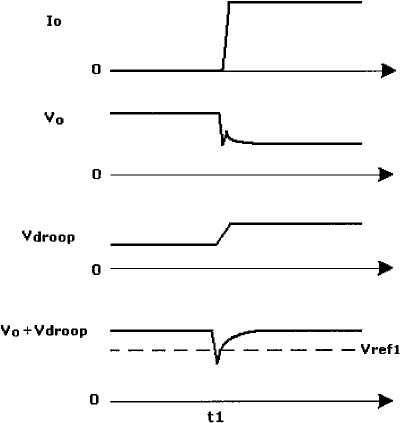
[0045] image 3 It is a schematic diagram of a load transi...


PUM


Abstract

The invention discloses a load transient change detecting circuit for a voltage converter, comprising an input terminal and a comparator, wherein the input terminal is connected with the output voltage terminal of the voltage converter through a resistor; and the comparator is used for comparing the voltage of the input terminal with a jump reference voltage and obtaining and outputting a load transient change signal of the output voltage parameter of the voltage converter. The load transient change detecting circuit has simple structure and can detect the load transient change of the voltage converter in time to control different output parameters of the voltage converter.

Description

technical field [0001] The invention relates to a voltage converter, in particular to a load transient change detection circuit for a Buck type voltage converter. Background technique [0002] The increasingly complex functions of contemporary electronic devices lead to large and rapid load changes and therefore place high demands on power supplies. The power supply requires a good transient response when the load changes transiently, and the circuit can be adjusted in time to obtain a stable output voltage and high efficiency. [0003] The timeliness of load transient change detection is a key link that affects the transient response speed. Transient response includes adjusting the circuit in time to make the output voltage smooth when the load changes, or adjusting the system frequency in time to improve system efficiency according to transient changes. The traditional means of smoothing the output voltage is to adopt the adaptive voltage positioning (AVP, Adaptive Volta...

Claims


Application Information

Patent Timeline
Patent Type & Authority Applications(China)
IPC IPC(8): H02M3/156
CPCH02M3/1584H02M3/158
Inventor 欧阳茜
Owner CHENGDU MONOLITHIC POWER SYST
Why Eureka
Try Eureka