Exhaust purification device for internal combustion engine

An exhaust purification device and technology for exhaust purification, which are applied in exhaust devices, mufflers, electrical control, etc., can solve the problems of catalyst overheating, time consumption, and fuel economy deterioration.

Inactive Publication Date: 2010-06-23
TOYOTA JIDOSHA KK
View PDF2 Cites 4 Cited by
  • Summary
  • Abstract
  • Description
  • Claims
  • Application Information

AI Technical Summary

Problems solved by technology

[0004] However, if it is desired to supply sufficient HC to the filter and increase the supply amount of HC, the NO x The heat generated in the catalyst increases, and the NO x Catalyst may overheat
On the other hand, if the amount of HC is limited to prevent overheating, the temperature of the filter will not rise sufficiently, or it will take time to rise to a sufficient temperature.
Fuel economy deteriorates as a result

Method used


Image

  • Exhaust purification device for internal combustion engine
  • Exhaust purification device for internal combustion engine
  • Exhaust purification device for internal combustion engine

Examples


Embodiment 1

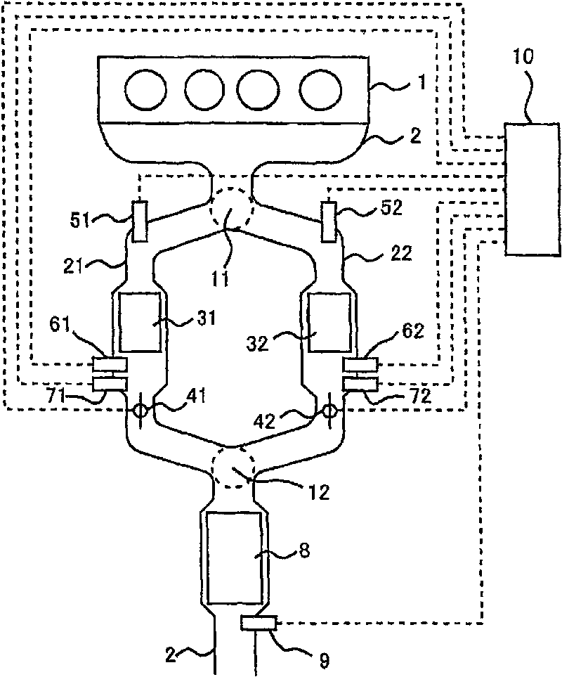
[0042] figure 1 It is a figure which shows the schematic structure of the internal combustion engine 1 and its exhaust system of this embodiment. figure 1 The internal combustion engine 1 shown in is a water-cooled four-stroke diesel engine.

[0043] An exhaust passage 2 leading to the combustion chamber is connected to the internal combustion engine 1 . The exhaust passage 2 is branched into a first exhaust passage 21 and a second exhaust passage 22 at a branch portion 11, and the first exhaust passage 21 and the second exhaust passage 22 join at a confluence portion 12 downstream of the branch portion 11. .

[0044] In the first exhaust passage 21, a first occlusion reduction type NO x Catalyst 31 (hereinafter referred to as the first NO x catalyst). In addition, in the second exhaust passage 22, a second occlusion reduction type NO x Catalyst 32 (hereinafter referred to as the second NO x catalyst). first NO x Catalyst 31 and the second NO x The catalyst 32 has a ...


PUM


Abstract

An exhaust purification device for an internal combustion engine, which, in regenerating a filter, quickly raises the temperature of the filter and suppresses overheating of exhaust purification catalysts located upstream of the filter. The exhaust purification device has an exhaust path (2) branched at a branch section (11) and merging at a merging section (12), the exhaust purification catalysts (31, 32) located between the branch section (11) and the merging section (12), the filter (8) located on the downstream of the merging section (12), reduction agent supply means (51, 52) for supplying reduction agents to their respective exhaust paths from the upstream of the exhaust purification catalysts (31, 32), and adjustment means (41, 42) for adjusting the amounts of exhaust gases passing through the exhaust purification catalysts (31, 32). To regenerate the filter (8), the reduction agent supply means (51) supplies the reduction agent, and the amount of the exhaust gas passing through the exhaust purification catalyst (31) located in the exhaust path (21), to which the reduction agent is supplied, is decreased.

Description

technical field [0001] The present invention relates to an exhaust purification device for an internal combustion engine. Background technique [0002] The following technology is known: the exhaust passage of an internal combustion engine is divided into two, and each of the branched exhaust passages has a storage reduction type NO x Catalyst (hereinafter referred to as NO x Catalyst), and there is a particulate filter (hereinafter referred to as filter) downstream of the position where the branched exhaust passages merge. x Catalyst, let the exhaust gas with lean air-fuel ratio pass through the NO of the other side x catalyst, thereby raising the temperature of the filter (for example, refer to Patent Document 1 (Japanese Patent No. 3758617)). [0003] That is, on one side of the NO x The heat generated in the catalyst, the NO in this side x Unreacted HC in the catalyst, and NO passing through the other side x Oxygen from the catalyst flows into the filter. Therefor...

Claims


Application Information

Patent Timeline
Patent Type & Authority Applications(China)
IPC IPC(8): F01N3/24B01D53/94F01N3/02F01N3/08F01N3/28F01N3/36F02D45/00B01D46/42
CPCF02D41/0275F01N2560/025B01D53/9495F01N3/0878F01N3/0814B01D53/944F02D41/1454F01N2560/14F01N13/02F01N3/0253B01D53/9431B01D2251/208F01N3/0842F02D41/029F01N3/0871F02D41/1495F02D41/1446B01D2255/9045F01N2560/06F01N13/04B01D53/96F01N13/009F01N13/011
Inventor 植田贵宣广田信也
Owner TOYOTA JIDOSHA KK
Why Eureka
Try Eureka