Pressure glue dipping system for laying layer of subsequent technique of composite material pultrusion product

A composite material, pressure dipping technology

Inactive Publication Date: 2010-06-30
HARBIN COMPOSITE EQUIP
View PDF0 Cites 5 Cited by
  • Summary
  • Abstract
  • Description
  • Claims
  • Application Information

AI Technical Summary

Problems solved by technology

[0003] The purpose of the present invention is to solve the problem that the raw materials in the infiltration system for the subsequent layup of composite pultruded products cannot be fully infiltrated, cannot meet the production requirements of high-performance composite pultruded products, and are inconvenient to operate, and further provide A pressurized impregnation system for composite pultrusion product subsequent process lamination

Method used


Image

  • Pressure glue dipping system for laying layer of subsequent technique of composite material pultrusion product
  • Pressure glue dipping system for laying layer of subsequent technique of composite material pultrusion product
  • Pressure glue dipping system for laying layer of subsequent technique of composite material pultrusion product

Examples


specific Embodiment approach 1

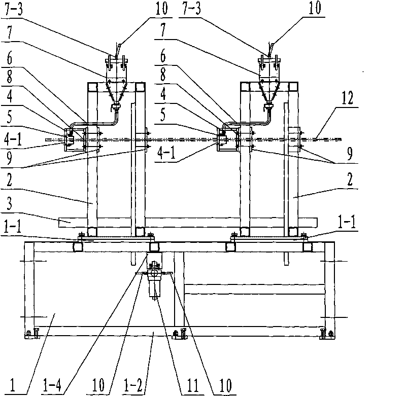
[0007] Specific implementation mode one: combine figure 1 with figure 2 To illustrate this embodiment, the pressurized rubber dipping system for subsequent process layup of composite pultrusion products in this embodiment includes a chassis 1, two support frames 2, two dipping ring supports 4, two pressurized dipping Ring 5, two rubber hoses 6, two pneumatic pressure rubber tanks 7, four tooling plates 9, two pressure air pipes 10 and a compressed air pressure adjustment valve 11; two supporting frames are installed side by side on the bottom frame 1 2. A dipping ring bracket 4 is installed on each of the two supporting frames 2, and each of the two dipping ring brackets 4 has a passage hole 4-1, and the passage holes 4-1 on the two dipping ring brackets 4 The axes are on the same horizontal line, and each of the two dipping ring brackets 4 is equipped with a pressurized dipping ring 5, and the axes of the two pressurized dipping rings 5 ​​are on the same level as the axis p...

specific Embodiment approach 2

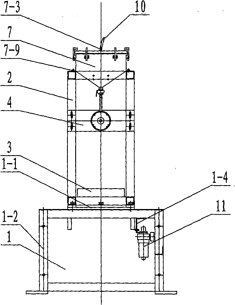
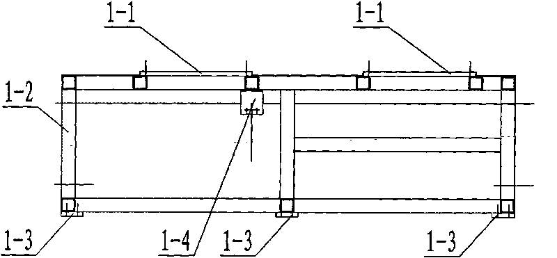
[0008] Specific implementation mode two: combination figure 1 with Figure 3-Figure 5 To illustrate this embodiment, the underframe 1 of this embodiment is composed of two supporting frame connecting plates 1-1, an underframe main body 1-2, a plurality of anchor plates 1-3 and a pneumatic regulating valve connecting plate 1-4, the underframe The main body 1-2 is a rigid structural frame welded by steel profiles and steel plates. The two support frame connecting plates 1-1 are installed side by side on the upper end surface of the chassis main body 1-2. The two support frames 2 are supported by The frame connecting plate 1-1 is connected with the chassis main body 1-2, the lower end of the chassis main body 1-2 is equipped with an anchor plate 1-3, and the compressed air pressure regulating valve 11 is connected to the bottom frame body 1-4 through the pneumatic regulating valve connecting plate 1-4 Installed inside the chassis main body 1-2. The function of such setting is t...

specific Embodiment approach 3

[0009] Specific implementation mode three: combination Figure 6-Figure 7 To illustrate this embodiment, each support frame 2 in this embodiment is a rigid structural frame welded from top to bottom by a support frame main body 2-1 and a connecting bottom plate 2-2. The role of such arrangement is to support components such as the dipping ring support 4 and the pressurized dipping ring 5 of the dipping system. Other compositions and connections are the same as those in Embodiment 1 or Embodiment 2.


PUM


Abstract

The invention relates to a pressure glue dipping system for laying a layer of the subsequent technique of a composite material pultrusion product, in particular to a glue dipping system for laying the layer of the subsequent technique of the composite material pultrusion product, aiming at solving the problems that in the existing dipping system for laying the layer of the subsequent technique of the composite material pultrusion product, raw materials can not be fully soaked, the demand of production of the high-performance composite material pultrusion product can not be met, and the operation is not convenient. A bottom frame of the pressure glue dipping system is provided with two supporting frames which are provided with glue dipping ring brackets that are internally provided with booster-type glue dipping rings; the upper ends of the brackets are provided with air-pressure-type pressure glue grooves, the lower ends of which are communicated with the glue dipping rings by glue conveying pipes, and the upper ends thereof are connected with compressed air pressure adjusting valves by pressure air pipes; and the supporting frames are provided with tooling plates. The pressure glue dipping system ensures the raw materials to be fully soaked, meets the demand of production of the high-performance composite material pultrusion product, and is convenient for operation.

Description

technical field [0001] The invention relates to a dipping system for subsequent process laying of composite pultruded products. Background technique [0002] Composite pultrusion products refer to continuous composite products with geometric cross-sectional shapes formed by composite pultrusion equipment through various processes. Common composite pultrusion profiles have been successfully used in industrial and construction industries, such as: chemical gratings, cable trays, rebar, window frames, etc. Due to the characteristics of light weight, high strength, corrosion resistance and designability of composite materials, more and more new-purpose products have been developed. Due to the different requirements of strength, stiffness, corrosion resistance and dielectric properties of composite pultruded products, the subsequent process layups are different, but there is one index that is the same, that is, sufficient infiltration between the resin and the reinforcing materi...

Claims


Application Information

Patent Timeline
Patent Type & Authority Applications(China)
IPC IPC(8): B29C70/34
Inventor 杨瑞庆刘永纯金永根李军英周放霍岩张华赵迎春
Owner HARBIN COMPOSITE EQUIP
Why Eureka
Try Eureka