Ring cooling machine and flue gas cover ring-shaped liquid groove thereof

A flue gas hood and liquid tank technology, applied in the field of iron and steel smelting, can solve the problems of increased rotation resistance of the inner annular liquid tank and the outer annular liquid tank, affecting the production process, and the ring cooler cannot work normally, and achieves a reasonable structure design. , Ensure assembly accuracy and improve the effect of assembly manufacturability

Active Publication Date: 2010-06-30
ZHONGYE-CHANGTIAN INT ENG CO LTD
View PDF0 Cites 7 Cited by
  • Summary
  • Abstract
  • Description
  • Claims
  • Application Information

AI Technical Summary

Problems solved by technology

[0008] However, subject to the positional relationship between the upper edge of the inner and outer side panels, the inner side edge of the inner and outer annular liquid tanks and the inner and outer sealing covers The dust and small particles in the fume hood can easily enter the inner and outer annular liquid tanks; in this way, after the dust and small particles accumulated in the inner and outer annular liquid tanks reach a certain height, the inner annular liquid tank and the The rotation resistance of the outer annular liquid tank increases, which may even cause the annular cooler to fail to work normally
In addition, when the above situation occurs, it can only be shut down for cleaning and maintenance operations, which will affect the entire production process

Method used


Image

  • Ring cooling machine and flue gas cover ring-shaped liquid groove thereof
  • Ring cooling machine and flue gas cover ring-shaped liquid groove thereof
  • Ring cooling machine and flue gas cover ring-shaped liquid groove thereof

Examples


Embodiment Construction

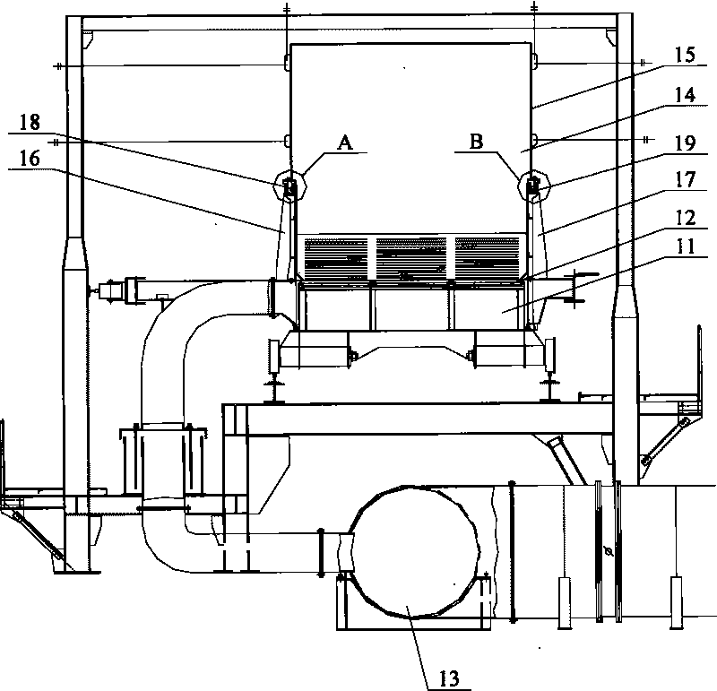
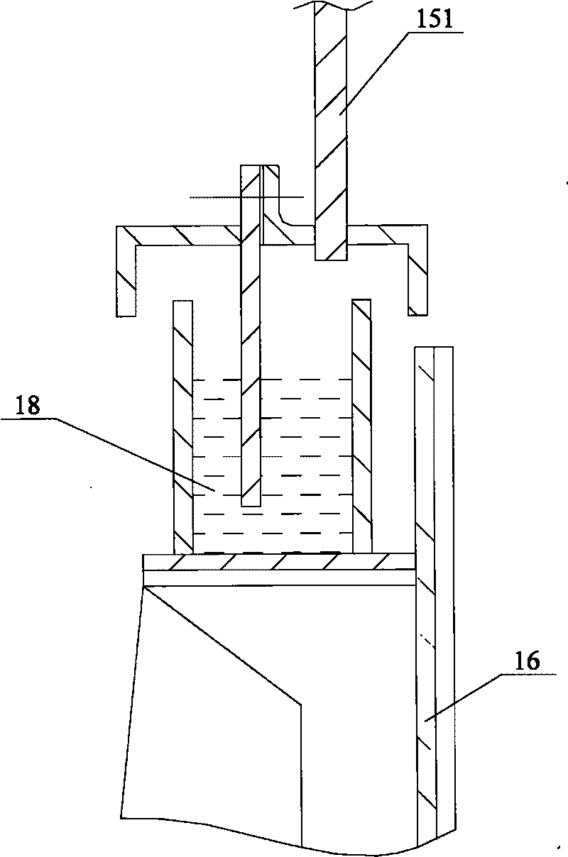
[0040] The core of the present invention is to improve the design of the structural relationship of the liquid seal of the flue gas hood, so as to ensure the reliable sealing between the flue gas hood and the trolley of the annular cooler, and improve the operation stability of the annular cooler.

[0041] Without loss of generality, this embodiment will be described in detail below in conjunction with the accompanying drawings.

[0042] The orientation words such as inner and outer involved in this article are defined based on the center of the annular cooler. It should be understood that the use of the orientation words such as inner and outer does not limit the scope of protection claimed in this application.

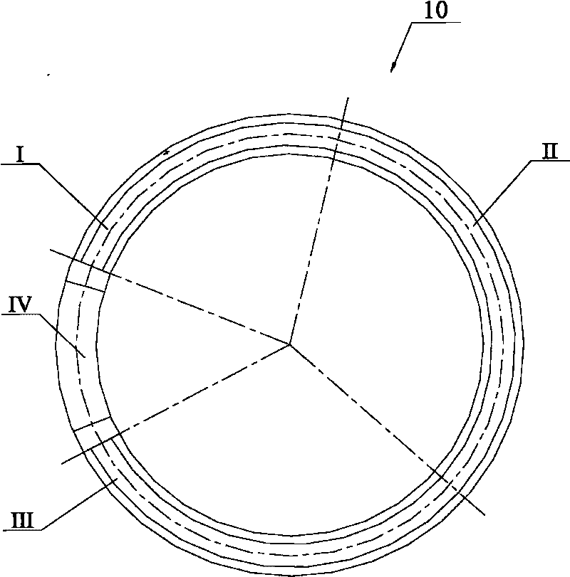
[0043] See Figure 5 , which is a radial sectional view of the annular cooler according to this embodiment.

[0044] The flue gas hood 51 is hoisted on the bracket 52 of the annular cooler 50 , and is in the shape of a ring concentric with the annular cooler 50 as a...


PUM


Abstract

The invention discloses a flue gas cover liquid seal, which is used between a flue gas cover and breast boards at the inner side and the outer side of a trolley, and comprises an internal ring-shaped liquid groove and an external ring-shaped liquid groove which are respectively arranged on the breast boards at the inner side and the outer side of the trolley, as well as an internal inserting plate and an external inserting plate; the internal inserting plate is fixedly connected with an inner side plate of the flue gas cover, and the lower edge of the internal inserting plate is arranged under the liquid level of the internal ring-shaped liquid groove and is provided with a gap with the bottom of the internal ring-shaped liquid groove; the external inserting plate is fixedly connected with an outer side plate of the flue gas cover, and the lower edge of the external inserting plate is arranged under the liquid level of the external ring-shaped liquid groove and is provided with a gap with the bottom of the external ring-shaped liquid groove; and the upper edges of groove side plates of the internal ring-shaped liquid groove and the external ring-shaped liquid groove close to the flue gas cover are respectively higher than the lower edges of the inner and the outer side plates of the flue gas cover. On the basis of ensuring reliable sealing between the flue gas cover and the trolley of a ring cooling machine, the operation stability of the ring cooling machine can be improved. On the basis, the invention also provides the ring cooling machine with the flue gas cover liquid seal.

Description

technical field [0001] The invention relates to the field of iron and steel smelting, in particular to an annular cooler and an annular liquid tank of a flue gas hood. Background technique [0002] In the iron and steel smelting process, the ring cooler is set between the sintering process and the mineral material feeding process to cool the sintered mineral material. The ring cooler is in the shape of a ring as a whole, and the sintered mineral material runs in the ring cooler for one week through the ring cooler trolley to complete the cooling of the mineral material. [0003] See figure 1 and figure 2 ,in, figure 1 is a schematic diagram of the overall structure of the ring cooler, figure 2 It is a radial (pointing to the center of the annular cooler) sectional view of the annular cooler. [0004] The annular cooler 10 is roughly divided into a high temperature zone I, a medium temperature zone II, a low temperature zone III and a non-cooling zone IV. During the w...

Claims


Application Information

Patent Timeline
IPC IPC(8): F27D15/02
Inventor 高德亮戴传德
Owner ZHONGYE-CHANGTIAN INT ENG CO LTD
Why Eureka
Try Eureka