
Double-coil four-string restrict constant current steel chord self-excited excitation circuit

A technology of exciting circuits and double coils, applied in the direction of using electric/magnetic devices to transmit sensing components, etc., can solve problems such as low frequency, electromagnetic interference oscillation, and the effect of obtained frequency.

Inactive Publication Date: 2010-06-30
邓铁六 +1
View PDF2 Cites 5 Cited by
  • Summary
  • Abstract
  • Description
  • Claims
  • Application Information

AI Technical Summary

Problems solved by technology

[0005] The main disadvantages of the exciter in the prior art are: (1) the exciter output and the induction input have a common ground, and the voltage drop of the exciter output on the common ground resistance of the cable for a long time is returned to the input terminal and often causes electromagnetic interference oscillation , so that the real frequency of the vibrating wire cannot be measured and the sensor fails; (2) In fact, what excites the steel string is the current pulse through the exciting coil, and the stronger the current pulse is, the greater the force pushing the steel string is
Now the output is voltage, the short-term resistance of the cable is small, the current is large, the excitation is strong, and the frequency obtained is high;
In short, the connecting cable should not be too long, otherwise the sensor may not be excited or electromagnetic interference oscillation may occur; and the frequency measured with a long cable is lower than that of a short cable, and the obtained frequency will be affected by the length of the cable

Method used


Image

  • Double-coil four-string restrict constant current steel chord self-excited excitation circuit
  • Double-coil four-string restrict constant current steel chord self-excited excitation circuit
  • Double-coil four-string restrict constant current steel chord self-excited excitation circuit

Examples


Embodiment Construction

[0014] The present invention will be further described below in conjunction with the drawings:

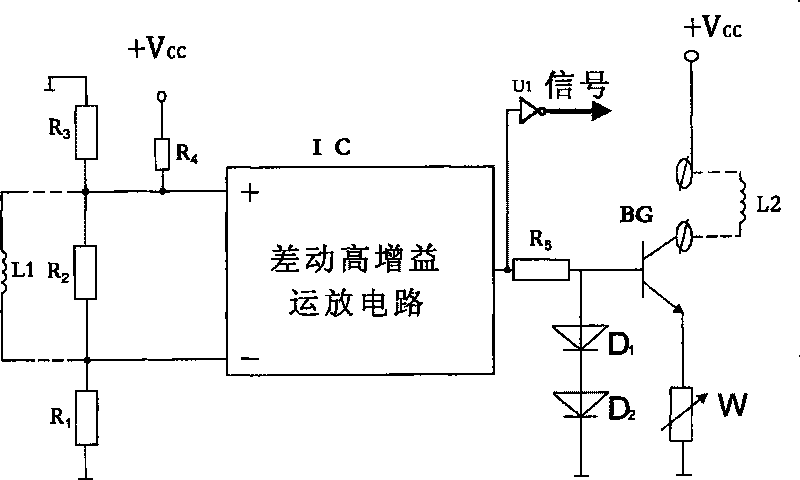
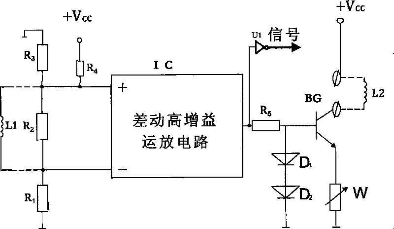
[0015] The electrical schematic diagram of the embodiment of the present invention is shown in the figure. The supply voltage is, for example, a 5V DC / DC isolation converter single power supply, the common terminal is 0V, and Vcc=5V. The sensor's induction coil L1 is connected to the input end of the differential high gain operational amplifier circuit through a pair of twisted pairs, R 1 R 2 R 3 Is the resistance attenuation network, R 2 Both ends are connected to the input end of the op amp, and its function is to attenuate differential mode interference; R 2 , R 3 One end is connected to the non-inverting input end and the inverting input end of the op amp, and the other end is connected to the common end to attenuate common mode interference. Resistance R 5 , Series silicon diode D 1 D 2 Connected to the base of the silicon transistor BG, the emitter of the BG is connected with an...


PUM


Abstract

The invention discloses a double-coil four-string restrict constant current steel chord self-excited excitation circuit, which comprises an induction coil L1 and an excitation coil L2, characterized in that both ends of the induction coil L1 are connected to the input end of a differential high-gain operational amplifier circuit through a pair of twisted-pair; the input end is connected to a resistor attenuation network performing functions of a differential mode and a common mode attenuation interference; the output end of the differential high-gain operational amplifier circuit is connected to the input end of a constant current power amplifier circuit with adjustable current; the constant current power amplifier circuit outputs current pulses with constant peak, is connected to the excitation coil L2 through a pair of twisted-pair; and receives steel chord frequency signals output from the output of the operational amplifier circuit through an inverter. The circuit can overcome the problems in the existing technology and the received frequency is not affected by cable length.

Description

Technical field [0001] The invention relates to the technical field of vibrating wire sensors, in particular to a dual-coil steel wire excitation circuit. Background technique [0002] The double-coil steel string excitation circuit (exciter) is a component used with the double-coil self-excited vibrating wire sensor, which plays a key role in ensuring that the sensor's vibrating wire frequency can be measured. In the past, the double-coil steel string excitation circuit of other manufacturers used a 3-core shielded cable to connect the excitation coil and the induction coil in the sensor, one of which was a common "ground wire", connected to the sensor housing and ground. The induction signal of the steel string vibration in the induction coil is amplified by the excitation circuit and output to the excitation coil in the form of voltage, forming a positive feedback to make the steel string vibrate. [0003] Another Chinese patent 98122129.7 discloses a single-coil current-type v...

Claims


Application Information

Patent Timeline
IPC IPC(8): G01D5/12
Inventor 邓铁六白泰礼
Owner 邓铁六
Learn More