Positioning method for digital electric valve

A valve positioning and electrical technology, applied in valve device, valve details, valve operation/release device, etc., can solve the problems of lack of overall concept of control system, decline of control quality, inability to eliminate deviation, etc., to improve the quality of control system, The effect of improving control quality and eliminating potential safety hazards

Inactive Publication Date: 2010-06-30
ZHEJIANG UNIV
View PDF0 Cites 17 Cited by
  • Summary
  • Abstract
  • Description
  • Claims
  • Application Information

AI Technical Summary

Problems solved by technology

First of all, the control system is designed based on the inherent flow characteristics of the control valve, and the actual working conditions of the control valve after it is put into operation are far from the test conditions of the inherent flow characteristics. Ignoring the objective fact that the working flow characteristics of the control valve is distorted will inevitably lead to control Quality decline; taking oil refining enterprises as an example, the pressure drop loss of the control valve accounts for about 20%-40% of the power consumption of the enterprise. With the decrease of the pressure drop ratio, the distortion of the working flow characteristics is more serious, and the negative impact on the control quality is catastrophic
Secondly, the valve position of the regulating valve adopts a 5-contact switch control algorithm. Although it has good robustness and fast dynamic response performance, it has the disadvantage of poor steady-state tracking ac

Method used


Image

  • Positioning method for digital electric valve
  • Positioning method for digital electric valve
  • Positioning method for digital electric valve

Examples


Embodiment Construction

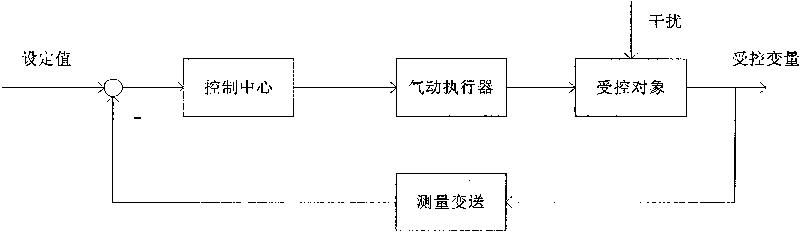
[0020] Such as figure 1 As shown, the pneumatic actuator is a part of the closed-loop process control system. Its function is to receive the control valve valve position given value signal from the control center, adjust the opening (flow) of the control valve, and make the valve affected by the disturbance deviate from the set value. The controlled variable returns to the set value. Therefore, when designing a pneumatic actuator digital electric valve positioner, in addition to considering the dynamic and static indicators of the pneumatic actuator itself, we must also pay attention to the control quality of the entire control system.

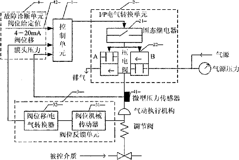
[0021] Such as figure 2 As shown, the control unit 1 in the digital electric valve positioner is connected with the I / P electrical conversion unit 2, the miniature pressure sensor, and the fault diagnosis unit 4. 4. The control unit 1 is connected; the pneumatic actuator is connected with the regulating valve, the valve position feedback un...


PUM


Abstract

The invention discloses a positioning method for a digital electric valve. A positioner consists of a control unit, an I/P electric conversion unit, a valve position feedback unit and a fault diagnosis unit. The positioning method includes the following steps: flow characteristic parameters of the positioner are configured; on the basis of providing the entire diversified flow characteristics and acting directions of an adjusting valve, correction is carried out aiming at work flow characteristic distortion caused by factors such as the change of the pressure drop ratio of the adjusting valve and the like; the valve position control of the adjusting valve is based on a Fuzzy-PI dual-mode non-interference switching algorithm; the fault diagnosis depends on internal relationships among a valve position given value, a valve position feedback value and valve film head pressure which are set by a control center, and a user selects to release or partially release the valve film head pressure when in valve stuck freeing operation according to the rule-based knowledge reasoning, so as to realize the fault diagnosis; the valve displacement/electric conversion of the valve position feedback unit depends on a non-contact magnetic sensitive potentiometer, the man-machine interaction adopts the touch screen technology, and the control unit accesses to a control network by an Ethernet interface.

Description

technical field [0001] The invention belongs to the technical category of valve positioner for electric regulating valves, and in particular refers to a valve positioner with the functions of distortion correction and fault diagnosis of the working flow characteristics of the regulating valve. Digital electro-valve positioner for valve displacement / electrical switching devices. Background technique [0002] Pneumatic actuators for industrial processes consist of electric valve positioners, pneumatic actuators and regulating valves. The basic function of the electric valve positioner is to control the difference between the given value of the valve position of the control valve output by the control center and the feedback value of the valve position of the control valve, and to control the pneumatic actuator and the opening of the control valve (flow rate) according to the preset algorithm. ), and the valve position feedback unit feeds back the real-time valve position valu...

Claims


Application Information

Patent Timeline
IPC IPC(8): G05D7/06F16K31/00
Inventor 吴宁宁吴明光栾振华
Owner ZHEJIANG UNIV
Why Eureka
Try Eureka