Shift register circuit

A shift register and circuit technology, applied in static memory, digital memory information, instruments, etc., can solve problems such as lowering display quality and image flickering

Inactive Publication Date: 2010-06-30
AU OPTRONICS CORP
View PDF0 Cites 13 Cited by
  • Summary
  • Abstract
  • Description
  • Claims
  • Application Information

AI Technical Summary

Problems solved by technology

However, each pulse of the plurality of gate signals is essentially an ideal square wave, so the falling edge of each pulse can pull down the written pixel voltage through the coupling operation of the parasitic capacitance of the pixel unit, which is the feedthrough effect ( Feed-through effect), which can easily lead to image flicker (Image Flicker), thus reducing the display quality

Method used


Image

  • Shift register circuit
  • Shift register circuit
  • Shift register circuit

Examples


Embodiment Construction

[0067] In the following, according to the shift register circuit of the present invention, specific embodiments are described in detail with accompanying drawings, but the provided embodiments are not intended to limit the scope of the present invention.

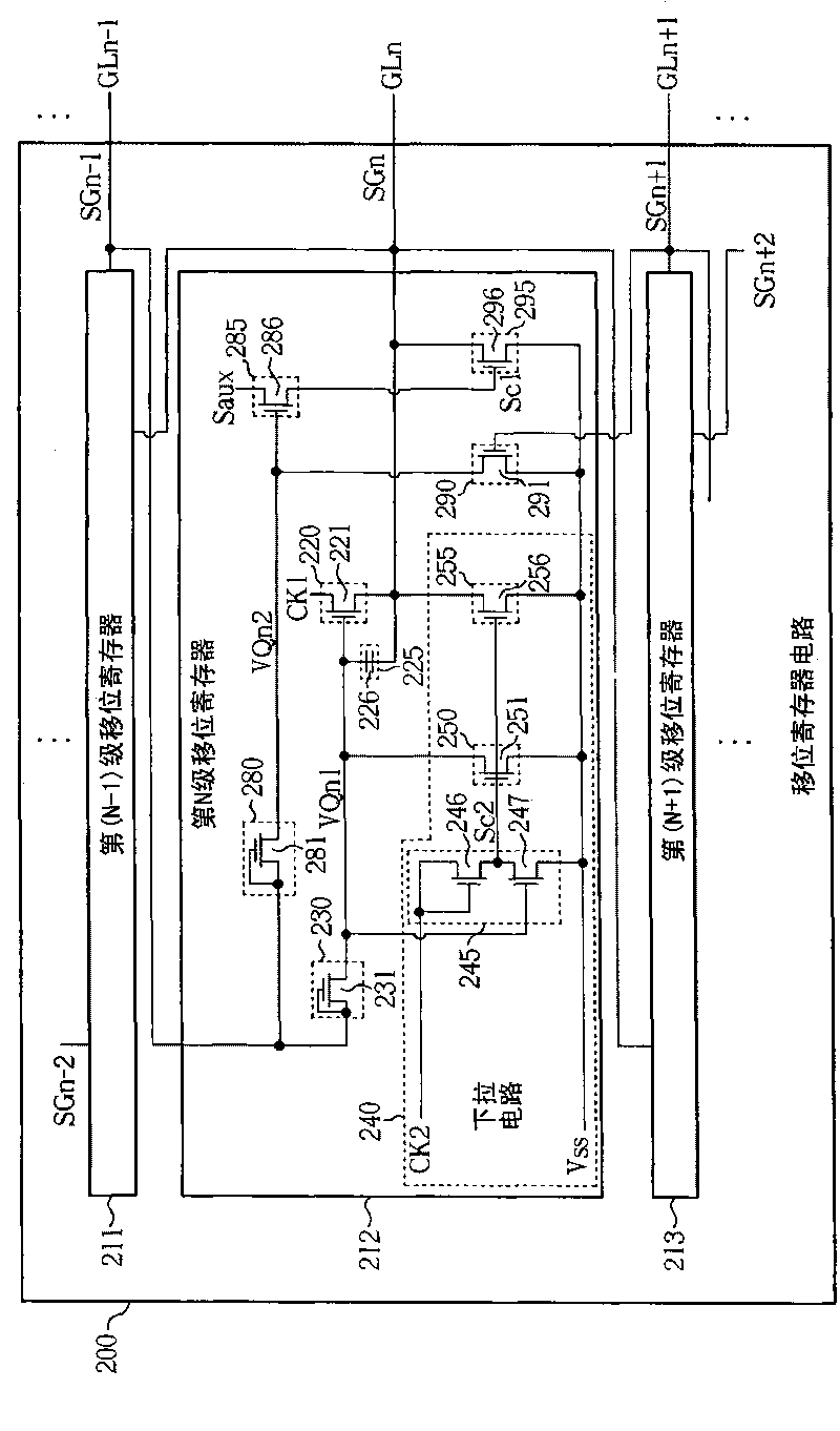
[0068] figure 2 It is a schematic diagram of the shift register circuit of the first embodiment of the present invention. Such as figure 2 As shown, the shift register circuit 200 includes a multi-stage shift register. For the convenience of illustration, the shift register circuit 200 only shows the (N-1)th shift register 211, the Nth shift register 212 and the (N+ 1) Stage shift register 213, wherein only the Nth stage shift register 212 shows the internal functional unit structure, and the rest of the stage shift registers are similar to the Nth stage shift register 212, so no further description is given. In the operation of the shift register circuit 200, the (N-1)th stage shift register 211 is used to provide the g...


PUM


Abstract

The invention relates to a shift register circuit with waveform chamfering function, which comprises multi-level shift registers. Each level of shift register comprises a first input unit, a pulling-up unit, a pulling-down circuit, a second input unit, a control unit and a waveform chamfering unit. The first input unit is used for outputting a first drive control voltage according to a first grid signal. The pulling-up unit is used for pulling a second grid signal up according to the first drive control voltage. The pulling-down circuit is used for pulling the first drive control voltage and the second grid signal down. The second input unit is used for outputting a second drive control voltage according to the first grid signal. The control unit is used for generating a control signal according to the second drive control voltage and an auxiliary signal. The waveform chamfering unit is used for executing waveform chamfering operation on the second grid signal according to the control signal. The invention can remarkably shorten the pressure difference of a pulse failing edge of a grid signal output by the shift register circuit so as to reduce the feed through effect, and can also lighten the image flicker phenomenon so as to improve the image display quality.

Description

technical field [0001] The invention relates to a shift register circuit, in particular to a shift register circuit with a waveform-shaping function. Background technique [0002] A liquid crystal display (Liquid Crystal Display; LCD) is a flat panel display widely used at present, which has the advantages of light and thin appearance, power saving and no radiation. The working principle of the liquid crystal display device is to change the arrangement state of the liquid crystal molecules in the liquid crystal layer by changing the voltage difference between the two ends of the liquid crystal layer, so as to change the light transmittance of the liquid crystal layer, and cooperate with the light source provided by the backlight module to display images. Generally speaking, a liquid crystal display device includes a plurality of pixel units, a source driver and a shift register circuit. The source driver is used to provide multiple data signals to multiple pixel units. The...

Claims


Application Information

Patent Timeline
IPC IPC(8): G11C19/00G11C19/28
Inventor 徐国华刘俊欣陈勇志林致颖
Owner AU OPTRONICS CORP
Why Eureka
Try Eureka