
Equalizing equipment for battery units of electric automobile

A technology for balancing equipment and electric vehicles, applied in electric vehicles, battery circuit devices, collectors, etc., can solve the problems of large operating current fluctuations, difficult control, high energy loss, etc., and achieve the effect of battery packs

Active Publication Date: 2010-06-30
INST OF ELECTRICAL ENG CHINESE ACAD OF SCI +1
View PDF4 Cites 38 Cited by
  • Summary
  • Abstract
  • Description
  • Claims
  • Application Information

AI Technical Summary

Problems solved by technology

[0005] The purpose of the present invention is to overcome the problems of complex structure, difficult control, high energy loss and low equalization efficiency of the prior art, especially for hybrid electric vehicle batteries, the operating current fluctuates greatly, and the charging and discharging conversion is frequent. The equalization method cannot meet the equalization requirements. A simple, efficient and reliable equalization device suitable for battery packs used in hybrid vehicles is proposed to solve the differences and mismatches between batteries caused by the impact of charging and discharging on battery performance and life, and improve battery pack performance. effective service life

Method used


Image

  • Equalizing equipment for battery units of electric automobile
  • Equalizing equipment for battery units of electric automobile
  • Equalizing equipment for battery units of electric automobile

Examples


Embodiment Construction

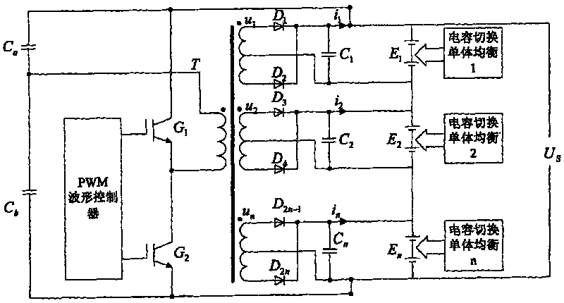
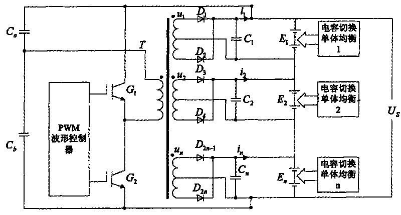
[0013] The equalizing device of the present invention is composed of two parts: an equalizing system of an inverter voltage-dividing battery group and an equalizing system of a capacitor switching unit. Among them, the inverter voltage dividing battery pack equalization system is composed of switching tube MOSFET, capacitor, diode and transformer, and the capacitor switching single balancing system is composed of switching tube MOSFET and capacitor.

[0014] like figure 1 As shown, n battery packs E1~En connected in series form a battery pack, where n is an integer greater than 0. When the battery pack is discharged, U S is the load voltage, when the battery pack is charging U S is the supply voltage. figure 1 The circuit schematic diagram mainly includes two parts, one part is the inverter voltage divider battery pack equalization system, which is composed of capacitor C a 、C b , switching tube MOSFET G 1 , G 2 , transformer T, protection diode D 1 ......D 2n And the ...


PUM


Abstract

The invention relates to equalizing equipment for battery units of an electric automobile, which comprises an inverse partial pressure battery unit equalizing system and a capacitor switching single equalizing system. In the inverse partial pressure battery unit equalizing system, two large capacitors which are connected in series are connected in parallel with a first switching tube MOSFET and asecond switching tube MOSFET which are connected in series to be crossed at two ends of the positive electrode and the negative electrode of a battery pack formed by connecting a plurality of batteryunits in series; the homonymous end of the primary side of a transformer is connected with the middle point of the large capacitors which are connected in series, and the heteronymous end of the transformer is connected with the source electrode of the first switching tube MOSFET; a multi-secondary side structure is adopted by the transformer; and the center tap of the secondary sides of the transformer is connected with the negative electrode of each battery unit. In the capacitor switching single equalizing system, four switching tubes MOSFET are connected in series in pairs; each series branch is respectively connected with the positive electrode and the negative electrode of two adjacent single batteries in each battery unit; and a filter capacitor is crossed with the middle point of the switching tubes MOSFET which are connected in series. The inverse partial pressure battery unit equalizing system equalizes a plurality of battery units which are connected in series, and the capacitor switching single equalizing system equalizes single battery in each battery unit.

Description

technical field [0001] The invention relates to a charging and discharging equalization device for series battery packs of electric vehicles. Background technique [0002] In recent years, as energy saving and environmental protection issues have been widely concerned by countries all over the world, the research on electric vehicles with advantages of cleanness, environmental protection and energy saving has entered a new period of development. Under the condition that pure electric vehicles cannot be fully marketed, hybrid electric vehicles as a transitional product are forming a new round of technology development hotspots. Storage battery will be the key to the development of hybrid electric vehicles as a power source. The battery used in hybrid electric vehicles generally consists of multiple single cells connected in series to form a module. Due to the dispersion of performance during the manufacturing process of the single battery and the non-uniformity of the inter...

Claims


Application Information

Patent Timeline
Patent Type & Authority Applications(China)
IPC IPC(8): H02J7/00
Inventor 王立业王丽芳佘沛亮孙权杨健徐冬平
Owner INST OF ELECTRICAL ENG CHINESE ACAD OF SCI
Learn More