Switched reluctance motor positioning control system

A switched reluctance, positioning control technology, applied in motor generator control, control system, electronic commutation motor control, etc., can solve the problem of insufficient output power, and achieve the effect of strong load capacity and high precision

Inactive Publication Date: 2010-06-30
BEIJING CHINA TEX MECHANICAL & ELECTRICAL ENG
View PDF0 Cites 2 Cited by
  • Summary
  • Abstract
  • Description
  • Claims
  • Application Information

AI Technical Summary

Problems solved by technology

In terms of disadvantages, the main reason is that due to the limitation of the step angle, the rotor cannot stop at any set a

Method used


Image

  • Switched reluctance motor positioning control system
  • Switched reluctance motor positioning control system
  • Switched reluctance motor positioning control system

Examples


Embodiment Construction

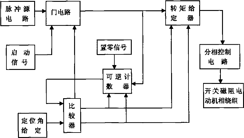
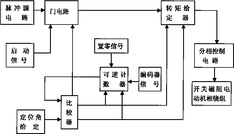
[0022] The present invention will be further described below in conjunction with the accompanying drawings and embodiments.

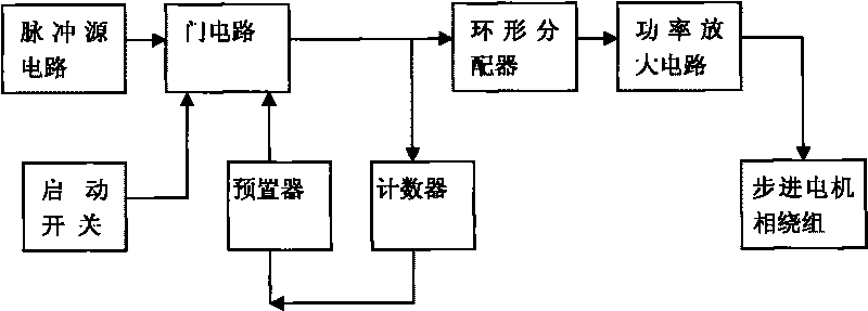
[0023] Such as figure 2 and 3 As shown, a switched reluctance motor positioning control system includes a switched reluctance motor and a controller; a switched reluctance motor is a motor whose rotor can be positioned at any set rotation angle; the controller consists of a pulse source circuit, a gate circuit, a torque Composed of a setter, a reversible counter and a comparator; the pulse source generates a pulse sequence representing a certain rotation angle interval, which is sent to the torque setter after passing through the gate circuit. The gate circuit is controlled by the start signal and the output of the comparator, and the comparator is controlled by the positioning Angle setting and the output control of the reversible counter, the reversible counter is controlled by the output of the comparator and the zero-setting signal, and the torque...


PUM


Abstract

The invention discloses a switched reluctance motor positioning control system. The system comprises a switched reluctance motor and a controller, wherein the switched reluctance motor is a motor that a rotor can be positioned at an arbitrary set angle; the controller consists of a pulse generating circuit, a gate circuit, a torque setter, a reversible counter and a comparer; a pulse source generates a pulse sequence representing a certain angle interval, and transmits the pulse sequence to the torque setter through the gate circuit; the gate circuit is controlled by output of an activating signal and the comparer; the comparer is controlled by orientation angle setting and the output of the reversible counter; the reversible counter is controlled by the output of the comparer and a zero setting signal; the torque setter is controlled by the output of the comparer; and output of the torque setter and the switched reluctance motor are winded. Positioning control has an open loop mode and a closed loop mode. The system can control a stepping motor to accurately step an arbitrary angle through a mode that two adjacent phases are electrified at the same time, and has high accuracy and strong load capacity.

Description

technical field [0001] The invention relates to a positioning control system of a switched reluctance motor, in particular to a positioning control system of a switched reluctance motor positioned at an arbitrary set rotation angle. Background technique [0002] At present, in the positioning system with rotation angle and displacement as the output, the simplest actuator is the stepper motor. The stepper motor converts the electrical pulse signal into angular displacement, and the total rotation angle of the rotor is proportional to the number of input pulses. In time, the angle of rotation is synchronized with the input pulse and the direction of rotation is in the order of energization of the phase windings. The motor has a fixed number of steps per revolution, the error will not accumulate, and no angular displacement sensor is needed. The motor also has self-locking capability if the energized state of the winding is not changed. [0003] An N-phase switched reluctan...

Claims


Application Information

Patent Timeline
IPC IPC(8): H02P6/00H02P6/24H02P6/08H02P8/22
Inventor 高超袭锦灼
Owner BEIJING CHINA TEX MECHANICAL & ELECTRICAL ENG
Why Eureka
Try Eureka