Method for sending and receiving clock signal as well as optical transmitter, optical receiver and system thereof

A clock signal and transmission method technology, applied in the field of optical communication, can solve the problems of rising system cost, complex implementation, low bandwidth utilization, etc., and achieve the effect of reducing maintenance cost, easy implementation, and reducing construction cost

Inactive Publication Date: 2010-06-30
HUAWEI TECH CO LTD
View PDF0 Cites 30 Cited by
  • Summary
  • Abstract
  • Description
  • Claims
  • Application Information

AI Technical Summary

Problems solved by technology

[0006] The above-mentioned existing clock signal transmission method needs to occupy a certain time slot or wavelength to realize, therefore, the bandwidth utilization rate is low, the network resources are wasted, and the network construction cost is increased.
In addition, the method of using OSC to transmit clock signals is inconsistent with the current communication standards, and it is more complicated to implement. In addition, for the metropolitan area wavelength division multiplexing system without OSC function, additional OSC needs to be configured, which will further increase the system cost. rise

Method used


Image

  • Method for sending and receiving clock signal as well as optical transmitter, optical receiver and system thereof
  • Method for sending and receiving clock signal as well as optical transmitter, optical receiver and system thereof
  • Method for sending and receiving clock signal as well as optical transmitter, optical receiver and system thereof

Examples


Embodiment 1

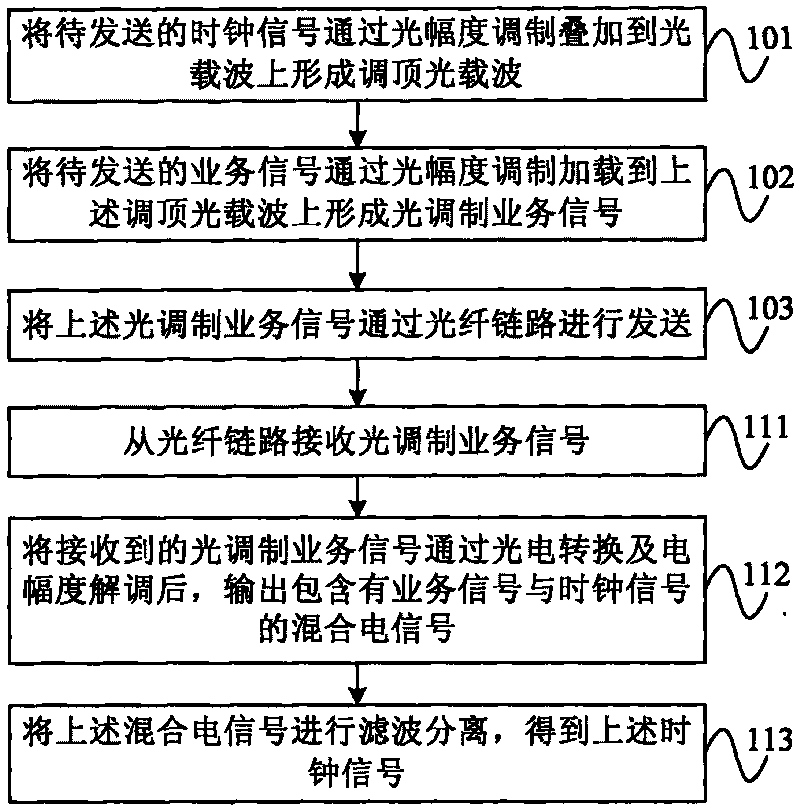
[0033] This embodiment provides a clock signal transmission method, such as figure 1 As shown, the following steps are included, wherein the steps 101-103 are the sending method of the clock signal; the steps 111-113 are the receiving method of the clock signal:

[0034] In step 101, a clock signal to be sent is superimposed on an optical carrier through optical amplitude modulation to form a top-tuned optical carrier.

[0035] Wherein, the clock signal refers to an electrical signal used to realize synchronization for an optical transmission system or equipment, and is usually a low-frequency, small-amplitude analog or digital electrical signal. For example, but not limited to, the 8MHz clock signal of the integrated system (Sysplex) timer of the SAN network server, the 2.048MHz, 2.048Mbit clock signal of the PDH, and the like. In this step, the clock signal is used as a top adjustment signal to modulate the optical carrier, so that the top envelope of the optical carrier ch...

Embodiment 2

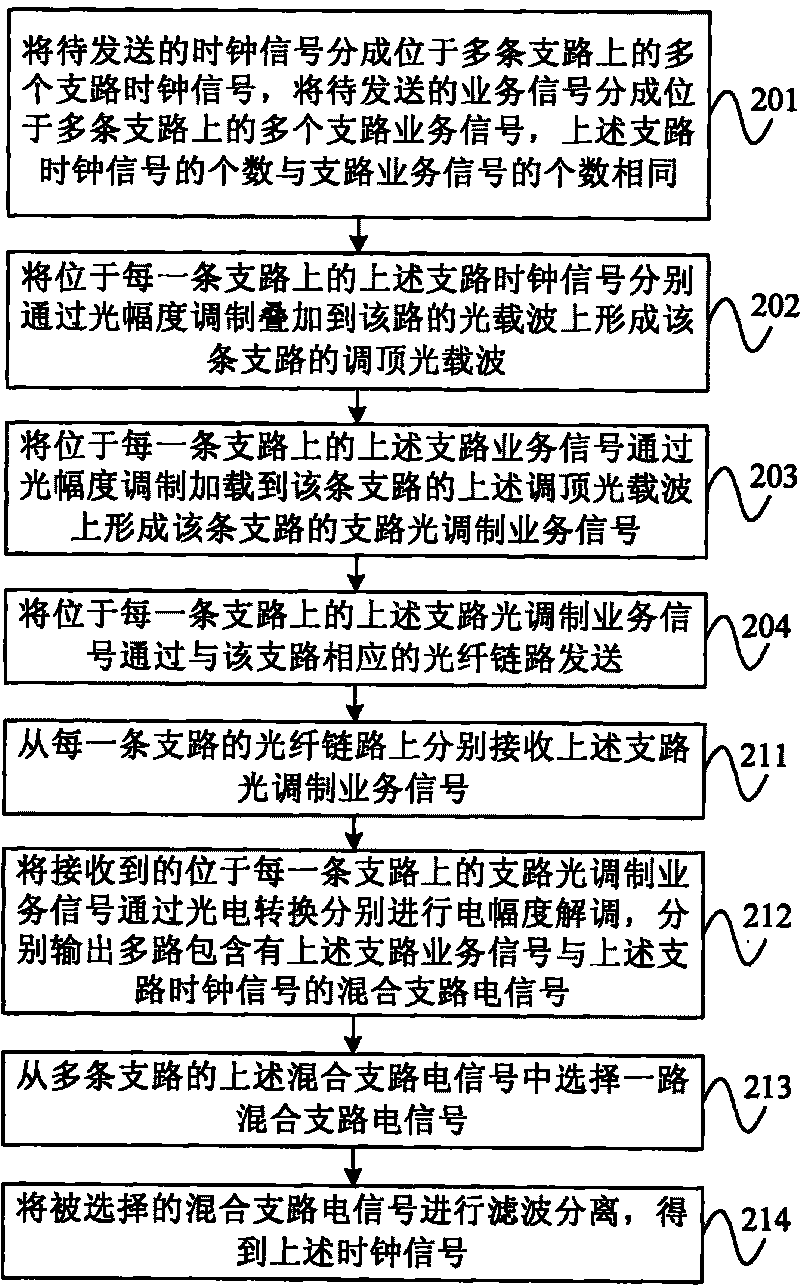
[0050] This embodiment provides another clock signal transmission method, such as figure 2 As shown, the following steps are included, wherein the steps 201-204 are the sending method of the clock signal; the steps 211-214 are the receiving method of the clock signal:

[0051] Step 201: Divide the clock signal to be sent into multiple branch clock signals located on multiple branch roads, divide the service signal to be sent into multiple branch service signals located on multiple branch roads, each of the above branch clock signals The number is the same as the number of the above branch service signals.

[0052] For example, the clock signal to be sent may be divided into two branch clock signals located on two branches; the service signal to be sent may be divided into two branch service signals located on two branches. Among them, compared with the original clock signal, the tributary clock signal has the same signal parameters as the original clock signal except that th...


PUM


Abstract

The invention relates to a method for sending and receiving a clock signal as well as an optical transmitter, an optical receiver and a system thereof. The sending method comprises superposing the following steps: a clock signal to be sent to an optical carrier by optical amplitude modulation to form a pilot tone modulated light carrier; superposing a service signal to be sent to the pilot tone modulated optical carrier by light amplitude modulation to form an optical modulation service signal; and sending the optical modulation service signal through a fiber link. The receiving method comprises the following steps: receiving an optical modulation service signal from a fiber link; outputting a mixed electrical signal including a service signal and a clock signal after photoelectric conversion and optical amplitude modulating are carried out to the received optical service-modulated signal; filtering the mixed electrical signal for separation to obtain the clock signal. The invention realizes receiving or unvarnished transmission of the clock signal without taking up other extra bandwidth or access resources of the optical transmission system, and greatly reduces network construction cost and maintenance cost, and is easy to realize.

Description

technical field [0001] The invention relates to a clock signal sending and receiving method, an optical transmitter, an optical receiver and an optical transmission system, belonging to the technical field of optical communication. Background technique [0002] The existing optical transmission system adopting Synchronous Digital Hierarchy (SDH for short) requires clock synchronization of the entire network, so it needs to be able to provide access functions for external synchronization signals or timing sources of synchronization equipment, and to be able to (Storage Area Network, SAN for short) carries or transmits a high-precision clock signal sent by a timing source. [0003] In the existing optical transmission system, the common clock signal transmission methods mainly include the following types: [0004] 1. In the SDH network, a 2M time slot is occupied to transmit the clock signal, such as: Plesiochronous Digital Hierarchy (PDH for short) clock signal; [0005] 2....

Claims


Application Information

Patent Timeline
Patent Type & Authority Applications(China)
IPC IPC(8): H04J14/02H04J3/06
CPCH04L7/0008
Inventor 常志文王士忠司明钢
Owner HUAWEI TECH CO LTD
Why Eureka
Try Eureka