Spiral separating device

A technology of separation device and vortex, which is applied in the direction of swirl device, separation method, and device whose axial direction of swirl can be reversed, etc. It can solve the problem of being easily taken away by the air flow again, affecting the separation effect, and increasing the system resistance, etc. question

Inactive Publication Date: 2012-01-04
长沙奥邦环保实业有限公司
View PDF1 Cites 0 Cited by
  • Summary
  • Abstract
  • Description
  • Claims
  • Application Information

AI Technical Summary

Problems solved by technology

The disadvantages are: firstly, because the cyclone separator is based on the structural principle of cyclone separation, the inner cavity of its shell is a sudden change section with a large upper part and a smaller lower part, the gas flow rate and pressure difference during operation change greatly, and the centrifugal force produced Part of the medium and coarse particles after preliminary separation by mutual friction and throwing are easily taken away by the airflow again due to the large pressure difference change, thus affecting the separation effect; The increase of the air flow velocity will lead to the increase of the resistance of the system and the increase of energy consumption; thirdly, the coarse and fine particles are separated by centrifugal movement along the inner wall of the shell, and the coarse particles are separated from the The friction generated by the inner wall of the housing is relatively high, so the housing components are prone to wear

Method used


Image

  • Spiral separating device
  • Spiral separating device
  • Spiral separating device

Examples


Embodiment 1

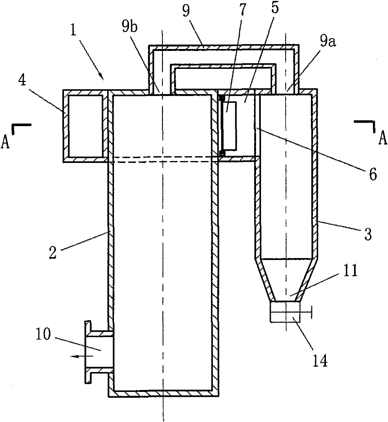
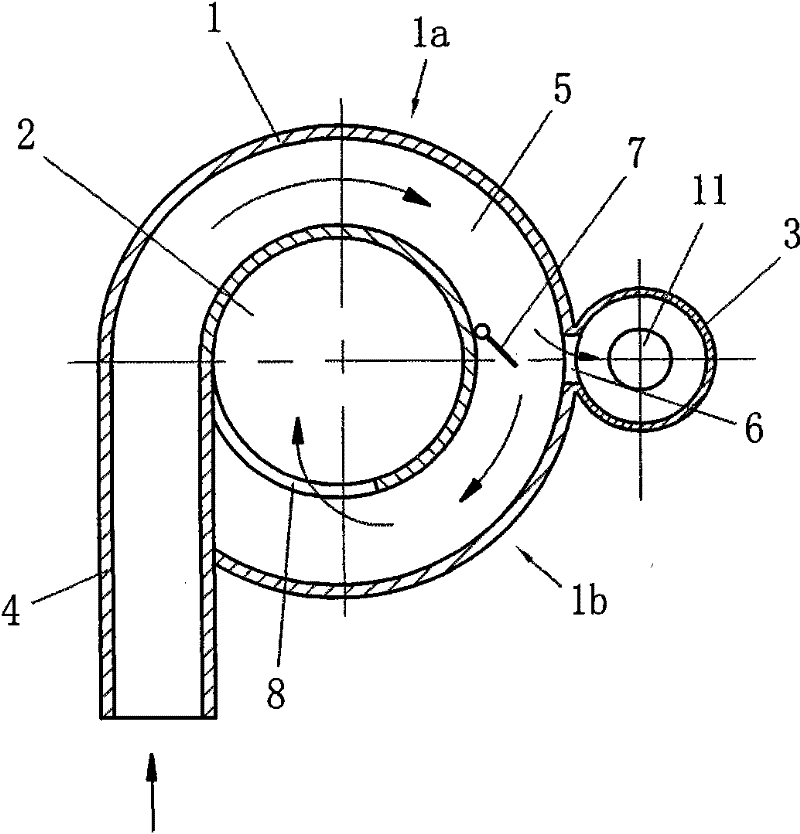
[0021] Example 1, see figure 1 , figure 2 .

[0022] A volute case 1, a main cylinder 2, and an auxiliary cylinder 3 are provided. The volute case 1 is provided with an air inlet pipe section 4, and the volute case 1 has a volute swirl air passage 5. The pipe hole of the air inlet pipe section 4 is connected to the The spiral swirl air passage 5 communicates; the upper part of the auxiliary cylinder 3 is located outside the volute case 1, and the upper part of the main cylinder 2 is located in the volute case 1. In this example, the upper wall of the main cylinder 2 forms a spiral spiral The inner wall of the flow air channel 5 and the outer wall of the middle section of the volute swirl air channel 5 are provided with a channel 6 communicating with the inner cavity of the auxiliary cylinder 3, and at least one deflector 7 is provided at the position of the channel 6 in the volute swirl air channel 5, The deflector 7 can swing freely under the action of the air flow, and re...

Embodiment 2

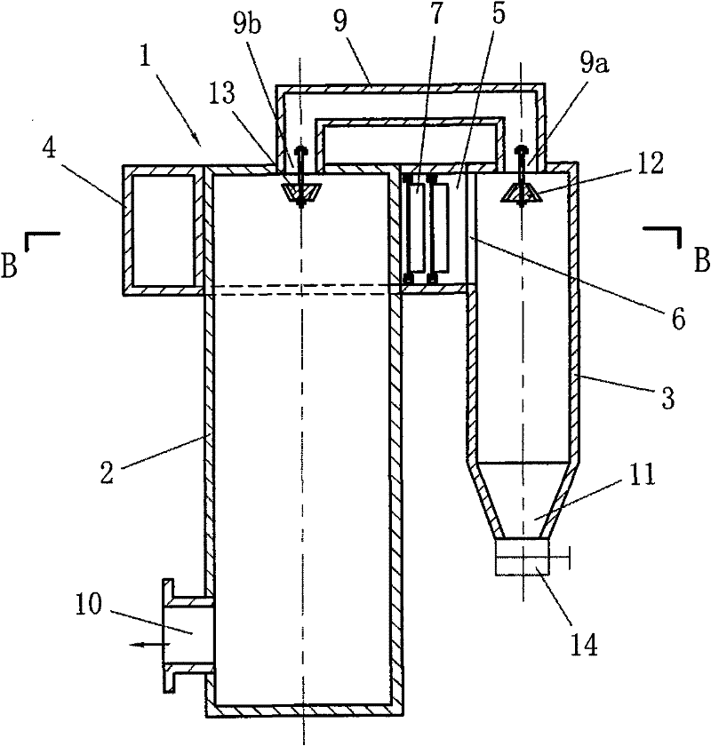
[0025] Example 2, see Figure 3 to Figure 6 .

[0026] This embodiment is based on the structure of Embodiment 1. A secondary separator 12 is provided at the first nozzle 9a of the pressure balance air duct pipe 9 communicating with the inner cavity of the auxiliary cylinder 3 to conduct secondary separator 12 on the particles entering the auxiliary cylinder. Secondary separation, the secondary separator 12 in this example is an upper cone secondary separator, the secondary separator 12 can also be a separator of other structural forms, and the diameter of the cone 12a bottom of the upper cone separator is larger than Or equal to the diameter of the first nozzle 9a of the pressure balance air duct pipe 9, during implementation, the diameter of the lower part of the cone 12a is preferably slightly larger than the diameter of the nozzle of the pressure balance air duct pipe 9, and the diameter of the upper part of the cone 12a is smaller than the first nozzle 9a diameter, the c...


PUM


Abstract

The invention discloses a spiral separating device. An air inlet tube section (4) is arranged on a spiral casing (1) and a spiral swirl air flue (5) is arranged in the spiral casing (1). The upper part of an assistant cylinder (3) is positioned outside the spiral casing (1) and the upper part of a main cylinder (2) is positioned inside the spiral casing (1). A passage (6) communicated with the inner cavity of the assistant cylinder (3) is arranged on the outer wall of the middle section of the spiral swirl air flue. At least one deflector (7) is arranged in the spiral swirl air flue and at the part of the passage (6), and an air flue (8) communicated with the inner cavity of the main cylinder (2) is arranged on the inner wall of the end section of the spiral swirl air flue. A first nozzle (9a) of a pressure balancing air flue tube (9) is communicated with the upper part of the inner cavity of the assistant cylinder (3) and a second nozzle (9b) is communicated with the upper part of the inner cavity of the main cylinder (2). An air outlet (10) is arranged at the lower part of the main cylinder (2) and a discharge hole (11) is arranged at the lower part of the assistant cylinder (3). A secondary separator (12) is arranged at the first nozzle (9a) and a pressure balancer (13) is arranged at the second nozzle (9b).

Description

Technical field [0001] The invention relates to a device for separating coarse and fine particles in an airflow, in particular to a separation device in the form of volute swirling flow. Background technique [0002] The utility model patent specification No. 200320130984.2 published on December 15, 2004 with the authorized announcement number CN2663009Y discloses a "high-efficiency cyclone separator". The separator includes a shell composed of a cylinder and a cone. The shell is provided with an air inlet pipe, a deflector, and an air outlet pipe. The lower part of the shell has a particle outlet. The structure is simple and has a good separation effect. The disadvantages are: firstly, because the cyclone separator is based on the structural principle of cyclone separation, the inner cavity of its shell is a sudden change section with a large upper part and a smaller lower part, the gas flow rate and pressure difference during operation change greatly, and the centrifugal f...

Claims


Application Information

Patent Timeline
Patent Type & Authority Patents(China)
IPC IPC(8): B01D45/16B04C5/103B04C11/00B04C9/00
Inventor 段若新王占国莫建炎
Owner 长沙奥邦环保实业有限公司
Why Eureka
Try Eureka