Cutting stress display device of full automatic inside diameter slicer with elastic feeding

A display device and inner circle slicing technology, which is applied in the direction of measuring/indicating equipment, metal processing machinery parts, metal processing equipment, etc., can solve the problems of low cutting speed, material damage, product concave center scrapping, etc., and avoid excessive force big effect

Inactive Publication Date: 2010-07-07
杨潇
View PDF0 Cites 4 Cited by
  • Summary
  • Abstract
  • Description
  • Claims
  • Application Information

AI Technical Summary

Problems solved by technology

[0016] The stepper motor is rigidly connected and the working mode is rigid force. The step amount of each step is applied to the cutting edge of the incision slicer. In practice, there are the following shortcomings: when the stepping feed speed is set relatively low, both The working conditions are basically similar. Under such working conditions, the cutting speed (cutting area per unit time) is relatively low, wh

Method used


Image

  • Cutting stress display device of full automatic inside diameter slicer with elastic feeding
  • Cutting stress display device of full automatic inside diameter slicer with elastic feeding
  • Cutting stress display device of full automatic inside diameter slicer with elastic feeding

Examples


Embodiment 1

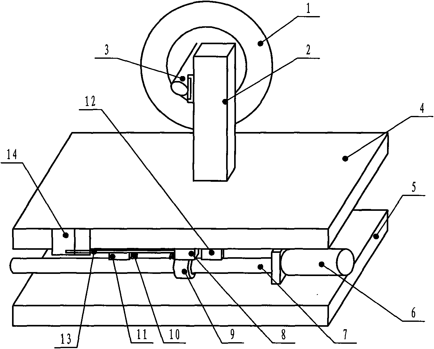
[0046] Example one: figure 1 As shown, this embodiment includes a cutting tool driven by a spindle motor 1, an X-axis moving table 4 driven by a stepping motor 6, and a Y-axis moving table 5 driven by a stepping motor. The X-axis moving table 4 is set on the Y axis. Above the mobile workbench 5, the X-axis mobile workbench 4 is provided with a clamping frame 2, and the displacement and force control transmission connection device between the X-axis mobile workbench 4 and the Y-axis mobile workbench 5 is provided with a spring 10 . The displacement and force control transmission connection device includes a stepping motor 6, a screw 7 is provided on the stepping motor 6, a screw nut 9 is sleeved on the screw 7, and the stepping motor 6 is fixedly installed on the Y axis to move and work On the table 5, the screw nut 9 is provided with a bearing block 8, one side of the bearing block 8 is connected with a spring 10, one end of the spring 10 is connected with the limiting block 11...

Embodiment 2

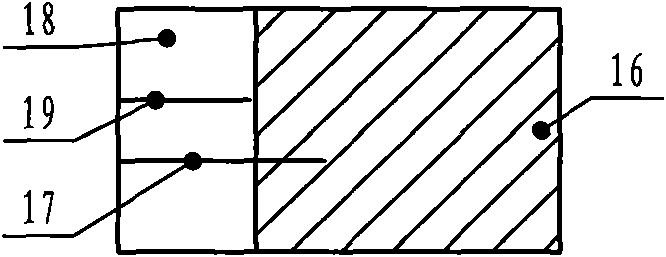
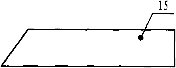
[0047] Embodiment two: figure 2 , image 3 As shown, the display window of this embodiment is provided with a transparent part 18, an opaque part 16, a limit working position line 19 and a normal working position line 17. The ruler 15 is a right-angle trapezoidal plate, and other structures are the same as the first embodiment.

Embodiment 3

[0048] Embodiment three: Figure 4 As shown, the display device is fixedly provided with a tension spring 30 on the X-axis moving table 4, one end of the tension spring 30 is fixed on the X-axis moving table, and the other end of the tension spring 30 is connected with an indicator needle plate 31 that can slide left and right. Connected, indexing marks are engraved on the indicating needle plate 31, the indicating needle plate 31 is covered by the display window 32, the indicating needle plate 31 is connected with the movable pulley 34, the movable pulley 34 is arranged on the pulley guide plate 35, and the movable pulley 34 is provided with an indicating needle plate Pull wire 33, one end of the indicator needle plate wire 33 is fixed on the X-axis moving table, the other end of the indicator needle plate wire 33 is connected to the indicator needle plate 31, one end of the displacement wire 36 is fixed on the screw nut assembly, and the displacement wire 36 The other end is f...


PUM


Abstract

The invention relates to a cutting stress display device of a full automatic inside diameter slicer with elastic feeding, belonging to the field of mechanical processing. The device comprises a cutter driven by a spindle motor and an elastic feeding device, wherein the elastic feeding device comprises an X axis mobile worktable driven by a stepping motor and a Y axis mobile worktable driven by a stepping motor; and the X axis mobile worktable is arranged above the Y axis mobile worktable. A connection device for controlling and transmitting the displacement and forces between the X axis mobile worktable and the Y axis mobile worktable is internally provided with a member with elastic function or an assembly with elastic function. The cutting stress display device is characterized in that a display device is arranged on the elastic feeding device, the display device comprises a measuring device and an indicating device; the display device is used for displaying the stress deformation amount of an elastic element, and the deformation amount can be used for indicating the stress working state of a cutting blade so as to determine and adjust cutting feeding parameters and overcome the influence of corresponding equipment, control modes and cutting parameters on different machinable materials, thereby avoiding accidents of blade and material damage caused by over large stress of the blade.

Description

Technical field: [0001] The invention belongs to a device of an automatic inner circle slicer, and in particular relates to a cutting force display device for an elastic feed automatic inner circle slicer. Background technique: [0002] The inner circle slicer is the most commonly used processing equipment in the plane cutting of sintered NdFeB rare earth permanent magnet materials. It includes semi-automatic inner circle slicer, automatic inner circle slicer, automatic inner circle slicer includes microcomputer control system, cutting tool driven by main motor, X-axis moving table driven by stepper motor, stepper motor The Y-axis moving table is driven, the X-axis moving table is set above the Y-axis moving table, and the stepping motor driving the X-axis moving table is set on the X-axis moving table. [0003] In the traditional manual control cutting process, the position of the cutting surface in the Y-axis direction is first displaced and positioned. After positioning, the h...

Claims


Application Information

Patent Timeline
IPC IPC(8): B23Q17/09
Inventor 杨潇
Owner 杨潇
Why Eureka
Try Eureka