
Numerical control machine tool main shaft structure

A technology of CNC machine tools and spindles, which is applied in the direction of metal processing machinery parts, large fixed members, maintenance and safety accessories, etc. It can solve the problems of burning spindle tools and affecting the processing accuracy, so as to avoid burning knives and improve processing safety Effect

Inactive Publication Date: 2016-10-12
SHENZHEN CREATE CENTURY MACHINERY
View PDF8 Cites 0 Cited by
  • Summary
  • Abstract
  • Description
  • Claims
  • Application Information

AI Technical Summary

Problems solved by technology

The heating of the spindle will affect the machining accuracy, and even cause the spindle or the tool to burn out in severe cases

Method used


Image

  • Numerical control machine tool main shaft structure
  • Numerical control machine tool main shaft structure
  • Numerical control machine tool main shaft structure

Examples


Embodiment Construction

[0023] In order to better understand the specific implementation process and implementation effect of the present invention, the following will be described in detail in conjunction with the accompanying drawings.

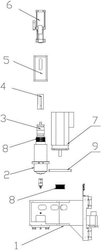
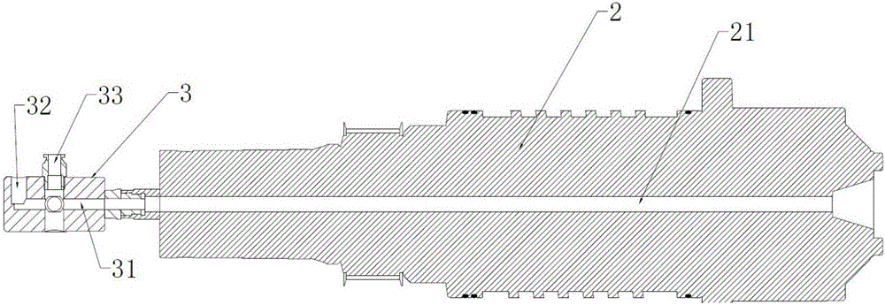
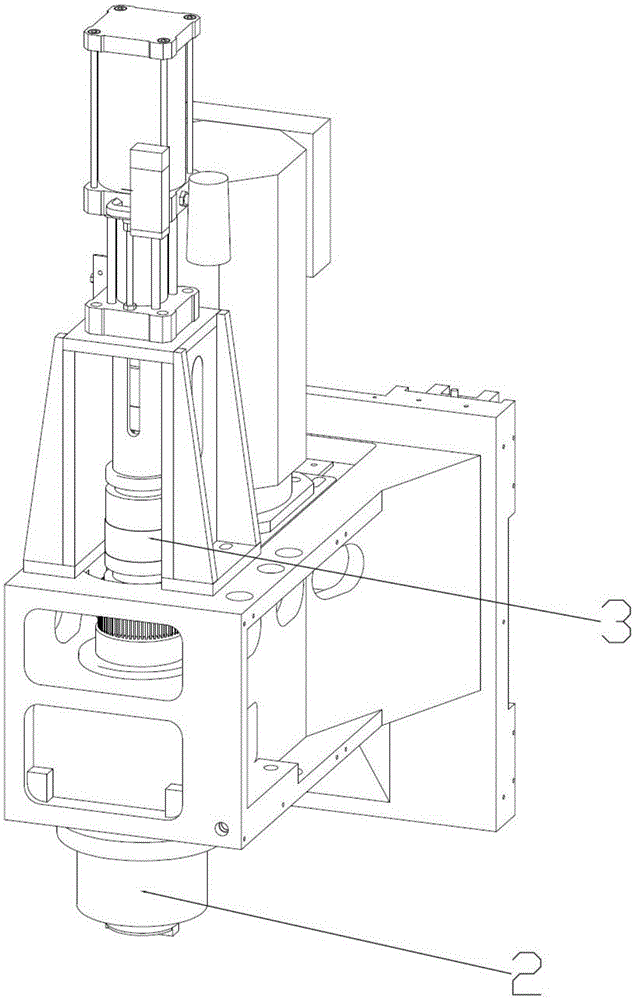
[0024] A CNC machine tool spindle structure, such as figure 1 , figure 2 and image 3 As shown, a spindle box 1 is included, and a spindle 2 is arranged on the spindle box 1, and the spindle 2 rotates relative to the spindle box 1 under the action of a motor.

[0025] Such as figure 2 As shown, the upper end of the main shaft 2 is provided with a columnar liquid outlet head 3 and is fixedly connected to one end of the columnar liquid outlet head 3, the other end of the liquid outlet head 3 is connected to the knife assembly, the main shaft is connected to the gear 8, and the motor 7 is also connected to the gear 8, the gear 8 of the motor 7 is connected with the gear 8 of the main shaft 2 through the belt 9, the motor 7 drives the main shaft 2 to rotate throug...


PUM


Abstract

The invention discloses a numerical control machine tool main shaft structure and belongs to the technical field of numerical control machine tools. The numerical control machine tool main shaft structure comprises a main shaft box, the main shaft box is provided with a main shaft, and the main shaft rotates relative to the main shaft box; the end above the main shaft is provided with a columnar fluid outlet head and connected with the bottom of the fluid outlet head, and the top of the fluid outlet head is connected with a knife beating assembly; the center of the main shaft is provided with a channel, the center of the fluid outlet head is provided with a fluid outlet channel, the side wall is provided with a fluid outlet, and the fluid outlet is communicated with the fluid outlet channel; cooling fluid reaches the fluid outlet channel of the fluid outlet head through the channel in the center of the main shaft and is released from the fluid outlet in the side wall. By means of the numerical control machine tool main shaft structure, the effects of automatic cooling and lubricating in the processing process of the main shaft structure are achieved.

Description

technical field [0001] The invention relates to the technical field of numerical control machine tools, in particular to a spindle structure of a numerical control machine tool. Background technique [0002] The main shaft is one of the important parts of the CNC machine tool. The processing tool is usually installed on the main shaft, and the main shaft drives the tool to process the product. The quality and maximum speed of the main shaft have a great influence on the processed product. [0003] Existing spindles are often accompanied by heat generation during high-speed machining or deep hole machining. The heating of the spindle will affect the machining accuracy, and even cause the spindle or tool to be burned out in serious cases. Contents of the invention [0004] In view of the above problems, the present invention provides a CNC machine tool spindle structure, which is provided with a cooling and lubricating structure for the spindle, which is used to cool and lu...

Claims


Application Information

Patent Timeline
Patent Type & Authority Applications(China)
IPC IPC(8): B23B19/02B23Q11/10
CPCB23Q1/70B23Q11/1015
Inventor 夏军罗育银叶李生李川
Owner SHENZHEN CREATE CENTURY MACHINERY
Learn More