Elevator and elevator noise reducing method
A technology for elevators and elevator passages, which is applied in the field of elevator and elevator noise reduction, can solve the problems of exhaustion of device life, and achieve the effect of prolonging the life of the device and reducing aerodynamic noise
- Summary
- Abstract
- Description
- Claims
- Application Information
AI Technical Summary
Problems solved by technology
Method used
Image

Examples
no. 1 approach
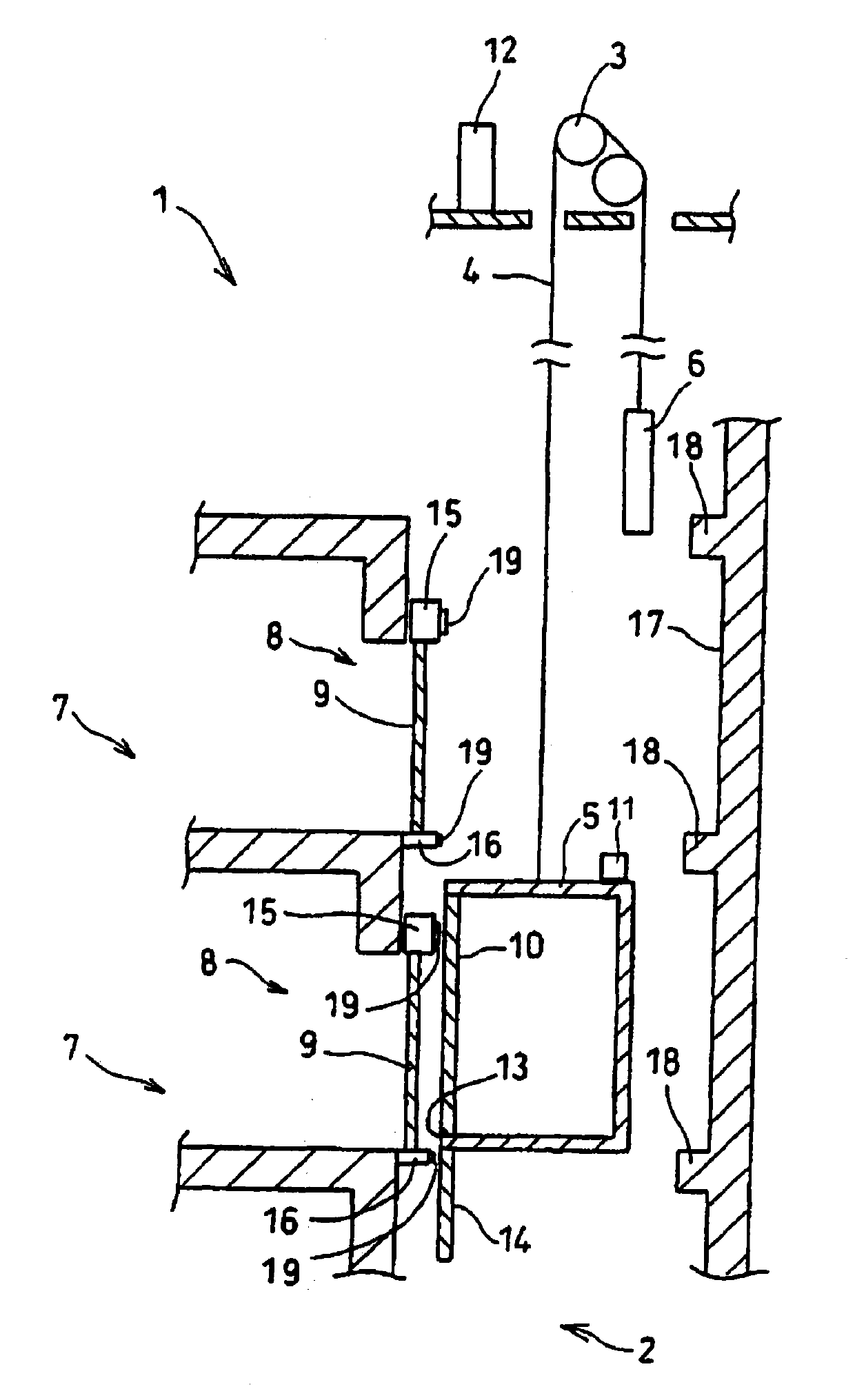
[0040] figure 1 It is a block diagram of an elevator according to the first embodiment of the present invention. The elevator 1 has a hoistway 2 in the building. A passenger car 5 is connected to one end of a cable 4 hanging down from a winch 3 in the hoistway 2 , and a counterweight 6 is connected to the other end. The passenger car 5 is provided with a car door 10 corresponding to the hall door 9 for opening and closing the entrance 8 of the elevator hall 7 of each floor.
[0041] The passenger car 5 is also provided with a car control device 11 for processing the operation content of the operating panel in the car and exchanging control signals with the outside of the car. Control signals can be exchanged between the car control device 11 and the control panel 12 through tail wires not shown in the figure or wirelessly. The power transmitted to the car control device 11 is provided by the control panel 12 or the power supply device in the hoistway 2 through the tail wire....
no. 2 approach
[0082] In the above-mentioned first embodiment and each modification, the airflow generating device 19 is fixedly installed on the hoistway 2 side, but the airflow generating device 19 may also be installed on the passenger car 5 side. Figure 8 It is the structure diagram of the elevator according to the second embodiment of the present invention. Among the symbols shown in this figure, those having the same symbols as those described above denote the same elements.
[0083] In the elevator 1A, a rectifying plate 28a is suspended from the front end of the sill receiving portion of the floor portion of the passenger car 5 . The rectifying plate 28a is a rectifying plate or a rectifying plate that doubles as a baffle. A rectifying plate 28b is provided on the upper portion of the passenger car 5 . Air flow generating devices 19 are respectively attached to the surfaces of these rectifying plates 28a and 28b on the side of the hall 7 .
[0084] These air flow generators 19 are ...
no. 3 approach
[0101] In the elevator according to the third embodiment of the present invention, the amount of airflow generated by the airflow generating device 19 can be changed according to whether the running direction of the passenger car 5 is the ascending direction or the descending direction. In a high-speed elevator, when the passenger car 5 is descending, if the descending speed of the passenger car 5 descends at the same speed as the ascending speed, the passengers in the car will feel discomfort such as earplugs or dizziness, and may have a feeling of falling . In this case, in terms of operation, the elevator is operated by setting the operating speed during the descending operation to be slower than the operating speed during the ascending operation.
[0102] In the elevator of this embodiment, when the running speed of the elevator car 5 is different during the ascending operation and the descending operation, the control panel 12 uses the signal indicating the ascending oper...
PUM
 Abstract
Description
Claims
Application Information
 - R&D Engineer
- R&D Manager
- IP Professional
- Industry Leading Data Capabilities
- Powerful AI technology
- Patent DNA Extraction
Browse by: Latest US Patents, China's latest patents, Technical Efficacy Thesaurus, Application Domain, Technology Topic.
© 2024 PatSnap. All rights reserved.Legal|Privacy policy|Modern Slavery Act Transparency Statement|Sitemap