Method for constructing quake-proof masonry house by utilizing prefabricated constructional column ring beams

A technology for constructing columns and houses, which is applied in the direction of building construction, earthquake resistance, construction, etc., can solve the problems of increased labor intensity of construction workers, lack of anti-seismic measures, and prolonging the construction period of houses, etc., to achieve good earthquake resistance, fast speed, The effect of low labor intensity

Inactive Publication Date: 2010-07-07
ZHENGZHOU UNIV
0 Cites 25 Cited by

AI-Extracted Technical Summary

Problems solved by technology

[0002] At present, most of the houses in urban areas and rural areas of our country are still of masonry structure. Most of them have not adopted any anti-seismic measures, and their seismic performance is very poor. Therefore, once a medium-scale earthquake occurs, these houses will collapse and damage. Huge loss of life and property
In order to overcome this problem, people add structural columns and ring beam structures on the basis of the original masonry str...

Abstract

The invention relates to a construction method of a quake-proof residential house, in particular to a method for constructing a quake-proof masonry house by utilizing prefabricated constructional column ring beams, which comprises the following steps of: firstly, prefabricating side columns, intermediate columns, beams, longitudinal beams, three-nodes, four-nodes and cored slabs; driving cinch bolts through circular holes arranged on connecting pieces; and respectively fixedly connecting the side columns, the intermediate columns, the beams and the longitudinal beams with the three-nodes or the four-nodes to construct the constructional column ring beam frames of the masonry house. In the invention, constructional columns, ring beams, the nodes and the cored slabs used for constructing the masonry house are prefabricated in a factory, and then the connection and the installation are carried out by adopting the cinch bolts in on-site construction. The construction is simple, the speed is high, the quality is reliable and the aseismic performance is good; in the construction process, a cast-in-place reinforced concrete wet operation process is completely canceled, large number of steel (wood) templates do not need to be purchased or hired and steel bar cutting equipment doe not need to be used, thereby reducing the on-site labor strength and saving construction cost.

Application Domain

Technology Topic

Image

  • Method for constructing quake-proof masonry house by utilizing prefabricated constructional column ring beams
  • Method for constructing quake-proof masonry house by utilizing prefabricated constructional column ring beams
  • Method for constructing quake-proof masonry house by utilizing prefabricated constructional column ring beams

Examples

  • Experimental program(1)

Example Embodiment

[0048] The present invention will be further described in detail below in conjunction with the accompanying drawings.
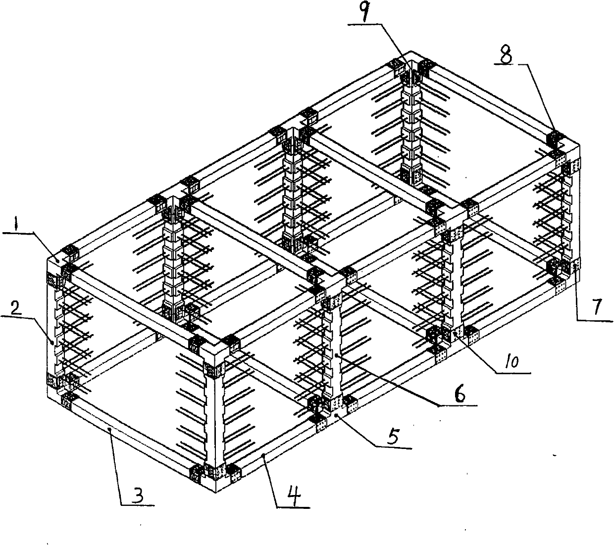
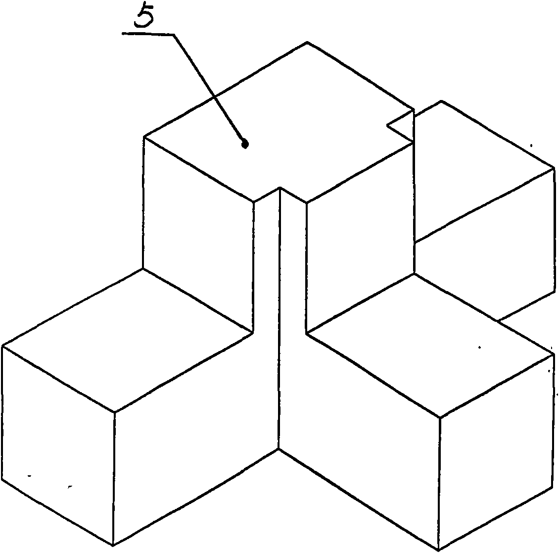
[0049] like figure 1 , 2, 3, 4, 5, 6, 7, 8, 9, and 10, the connector 7 is a welded composite steel plate with a cross-sectional shape of "L" shape, and round holes are arranged on both faces, and each face The number of round holes set is eight, and the connecting piece 8 and the connecting piece 10 are all welded composite steel plates with a cross-sectional shape of "U" shape, and round holes are arranged on three faces, and the number of round holes set on each face They are all eight, and the connecting piece 9 is a steel plate with a cross-sectional shape of "one", and eight round holes are set on the steel plate, and the adjacent two cylindrical surfaces of the side column 2 are horse-shaped and are provided with tie bars 11, The three adjacent cylinder surfaces of the central column 6 are prefabricated into a horse-toothed shape, and two symmetrical horse-toothed cylinders are provided with tie bars 12, and the other horse-toothed cylinder is provided with tie bars 11. The knot reinforcing bar 12 is a through bar, which runs through the whole center column 6 and is symmetrically distributed on both sides of the center column.
[0050] To use prefabricated side columns 2, central columns 6, beams 4, longitudinal beams 3, three nodes 1, four nodes 5 and hollow slabs to build a single-story three-bay seismic masonry structure house, including the following process steps:
[0051] The first step, prefabricated column beams and joints:
[0052] Prefabricate four side columns 2, four central columns 6, twelve beams 4, eight longitudinal beams 3, eight three-nodes 1, eight four-nodes 5 and several hollow slabs with reinforced concrete, and prepare eight connectors 7 , forty connectors 8, twenty-four connectors 9, eight connectors 10;
[0053] The second step, foundation construction:
[0054] Select the foundation form according to the geological conditions of the proposed building site, and carry out foundation construction;
[0055] The third step, geosphere beam construction:
[0056] a. After the foundation is constructed to the set elevation, a layer of cement mortar is evenly laid on the top surface of the foundation, and then four three-nodes 1 are placed at the intersection of the longitudinal wall foundation and the transverse wall foundation at the four corners of the house, and the four four-nodes 5 Place it at the junction of the longitudinal wall foundation and the transverse wall foundation in the middle of the house, and fix the three nodes 1 and the four nodes 5 on the foundation;
[0057] b. Place the crossbeam 4 on the foundation of the crosswall, assemble the two ends of the crossbeam 4 with its adjacent three-node 1 or four-node 5 respectively, and then wrap the connector 8 on the interface between the crossbeam 4 and the three-node 1 or four-node 5 , the cross-sectional shape of the connector 8 is a "U"-shaped welded composite steel plate, the opening of the "U"-shaped welded composite steel plate is buckled downward on the interface between the beam 4 and the three-node 1 or four-node 5, and passes through the round hole on the steel plate Drive expansion anchor bolts into the crossbeam 4 or the three-node 1 or the four-node 5, so that the crossbeam 4 is fixedly connected with the three-node 1 and the four-node 5, repeat this step, and fix the six crossbeams 4 on the foundation of the cross wall respectively;
[0058] c. Place the longitudinal beam 3 on the foundation of the longitudinal wall, assemble the two ends of the longitudinal beam 3 with the adjacent three-nodes 1 or four-nodes 5 respectively, adopt the fixed connection method of the crossbeam 4 in step b, and connect the longitudinal beam 3 with the adjacent three-node 1 or four-node 5 The three nodes 1 and the four nodes 5 are fixedly connected, repeat this step, and fix the four longitudinal beams 3 on the longitudinal wall foundation respectively;
[0059] The fourth step, column construction:
[0060] a. Assemble the side column 2 and the upward extremity of the three-node 1, and then wrap the connecting piece 7 and two connecting pieces 9 on the interface between the side column 2 and the three-node 1, and the connecting piece 7 is wrapped in a non-butterfly On the two sides of the two connecting pieces 9 are respectively wrapped on the two sides where the horse teeth are set, and then through the connecting piece 7 and the round hole on the connecting piece 9, the expansion joint is driven into the side column 2 or the three-node 1 Anchor bolts, fixedly connect the side columns 2 to the three-nodes 1, repeat this step, and fixedly connect the four side columns 2 to the four three-nodes 1 respectively;
[0061] b. Assemble the center column 6 with the four-node 5, and then wrap the connector 10 and a connector 9 on the interface between the center column 6 and the four-node 5, and wrap the connector 10 on the side without the horse teeth and its adjacent On the two sides of each other, one connecting piece 9 is wrapped on the other side, and then through the round hole on the connecting piece 10 and the connecting piece 9, the expansion anchor bolts are driven into the central column 6 or the four nodes 5, and the central column 6 Fixed connection with the four nodes 5, repeat this step, respectively fixedly connect the four center columns 6 with the four four nodes 5;
[0062] The fifth step, wall construction:
[0063] Build the transverse wall on the beam 4 and the longitudinal wall on the longitudinal beam 3 until the height of the transverse wall and the height of the longitudinal wall reach the set elevation of the bottom of the roof ring beam. When building the wall, ensure that the side column 2 and the tie bars on the center column 6 are built into the cement mortar layer of the wall. When building the wall, the positions of doors and windows and the operation space for installing the roof ring beam are reserved. The operation space for installing the roof ring beam refers to When installing the roof ring beam, the operation space required for flip-chip fixing the three nodes 1 on the side column 2, and the operation space required for flip-chip fixing the four nodes 5 on the center column 6;
[0064] The sixth step, roof ring beam construction:
[0065] a. When the height of the wall is built to the set height of the bottom of the roof ring beam, install the three nodes 1 upside down on the upper end of the side column 2 and fix them. The fixed connection method is the same as the fourth step, step a of the column construction. The side column 2 is fixedly connected to the three-node 1 in the same way, and the three-node 1 is flipped and fixedly connected to the side column 2, and this step is repeated, and the four three-nodes 1 are fixed upside down on the four side columns 2 respectively;
[0066] b. Put the four nodes 5 upside down on the upper end of the center column 6 and fix them. The fixed connection method is the same as that of the fourth step. Fix it upside down on the center pillar 6, repeat this step, and fix the four four-nodes 5 upside down on the four center pillars 6 respectively;
[0067] c. Lay a layer of cement mortar evenly on the top surface of the masonry wall, place the crossbeam 4 on the crosswall, and assemble the two ends of the crossbeam 4 with the adjacent three-node 1 or four-node 5 respectively, and its fixed connection mode Same as the third step, the fixed connection method of the crossbeam 4 in step b in the construction of the geosphere beam is the same, fix the crossbeam 4 with the three nodes 1 or the four nodes 5, repeat this step, and fix the six crossbeams 4 on the cross wall respectively ;
[0068] d. Place the longitudinal beam 3 on the longitudinal wall. The two ends of the longitudinal beam 3 are respectively assembled with the adjacent three-nodes 1 or four-nodes 5. The fixed connection method is the same as that in the third step, step b in the construction of the ground circle beam The fixed connection mode of the crossbeam 4 is the same, the longitudinal beam 3 is fixed with the three-node 1 or the four-node 5, repeats this step, and the four longitudinal beams 3 are respectively fixed on the longitudinal wall;
[0069] e. In the fifth step, in the wall construction step, the reserved roof ring beam operation space is completely masonry;
[0070] The seventh step, roof panel construction:
[0071] Spread a layer of cement mortar evenly on the top surface of the roof ring beam, and place the prefabricated concrete hollow slab on the top surface of the roof ring beam;
[0072] The eighth step, post-construction:
[0073] Install doors and windows, level the cement mortar floor, paint the walls inside and outside, and construct the roof.
[0074] Finally, it should be noted that the above-mentioned embodiments are illustrations rather than limitations to the technical solutions of the present invention, equivalent replacements by those of ordinary skill in the art or other modifications made according to the prior art, as long as they do not exceed the technical solutions of the present invention Both ideas and scope should be included in the scope of rights required by the present invention.

PUM

no PUM

Description & Claims & Application Information

We can also present the details of the Description, Claims and Application information to help users get a comprehensive understanding of the technical details of the patent, such as background art, summary of invention, brief description of drawings, description of embodiments, and other original content. On the other hand, users can also determine the specific scope of protection of the technology through the list of claims; as well as understand the changes in the life cycle of the technology with the presentation of the patent timeline. Login to view more.

Similar technology patents

Shock absorbing apparatus

InactiveUS6964451B1Easy constructionSuitable for retrofit into existing vehiclePedestrian/occupant safety arrangementElastic dampersEnergy absorbingIn vehicle
Owner:BERGEY KARL H

Classification and recommendation of technical efficacy words

  • Easy construction
  • Accelerate

Hand-held machine tool

Owner:ROBERT BOSCH GMBH
Why Eureka
Try Eureka