Optical fiber dispersion measuring apparatus

A technology for optical fiber dispersion and measuring instruments, which is applied in optics, instruments, optical components, etc., can solve the problems of high measurement cost and low measurement accuracy, and achieve the effects of high detection efficiency, simple measurement method, and simple structure

Inactive Publication Date: 2010-07-07
XI'AN INST OF OPTICS & FINE MECHANICS - CHINESE ACAD OF SCI
View PDF0 Cites 5 Cited by
  • Summary
  • Abstract
  • Description
  • Claims
  • Application Information

AI Technical Summary

Problems solved by technology

[0003] The purpose of the present invention is to provide a fiber optic dispersion measuring instrument, which solves the technical problems of low measurement accuracy and high measurement cost in the background art

Method used


Image

  • Optical fiber dispersion measuring apparatus
  • Optical fiber dispersion measuring apparatus

Examples


Embodiment Construction
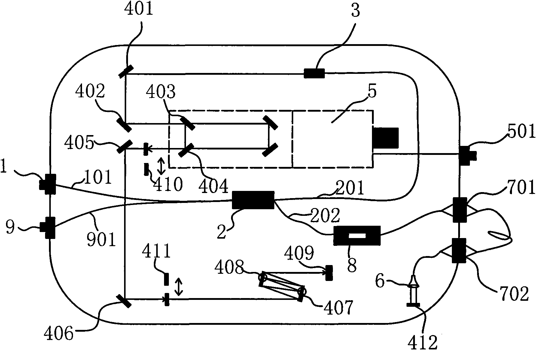
[0015] see figure 1

[0016] An optical fiber dispersion measuring instrument comprises: a broadband light source input port 1, the broadband light source input port 1 being a standard FC / PC pluggable optical fiber interface. The fiber coupler 2 arranged at the output end of the broadband light source input port 1; the collimator 3 arranged at the output end of the fiber coupler 2 connected through the optical fiber 201; the first reflector 401 arranged at the output end of the collimator 3 along the optical path in sequence , the second reflector 402, the third reflector 403, the fourth reflector 404, the tenth reflector 410, the fifth reflector 405, the sixth reflector 406; the sixth reflector 406 is also arranged in turn along the reflection optical path There are the eleventh reflector 411, the seventh reflector 407, the eighth reflector 408, and the ninth reflector 409; the optical fiber adapter 701, the optical fiber adapter 702, the microscopic The objective lens 6 an...


PUM


Abstract

The invention relates to an optical fiber dispersion measuring apparatus, which comprises a broadband light source input port, an optical fiber coupler, a collimator, a first reflecting mirror, a second reflecting mirror, a third reflecting mirror, a fourth reflecting mirror, a tenth reflecting mirror, a fifth reflecting mirror, a sixth reflecting mirror, a first optical fiber adapter, a second optical fiber adapter, a micro objective, an twelfth reflecting mirror, an electric translation platform, an electric translation platform control port and an interference light output port. The optical fiber coupler is arranged on the output end of the broadband light source input port; the collimator is arranged on the output end of the optical fiber coupler and is connected through an optical fiber; the first reflecting mirror, the second reflecting mirror, the third reflecting mirror, the fourth reflecting mirror, the tenth reflecting mirror, the fifth reflecting mirror and the sixth reflecting mirror are arranged on the outlet end of the collimator in sequence along a light path; the first optical fiber adapter, the second optical fiber adapter, the micro objective and the twelfth reflecting mirror are arranged on the output end of the optical fiber coupler and are connected through optical fibers in sequence; the electric translation platform and the electric translation platform control port are respectively arranged on the lower ends of the third reflecting mirror and the fourth reflecting mirror; and the interference light output port is arranged on the output end of the optical fiber coupler after interference and is connected through an optical fiber. The invention solves the technical problems of the prior art such as low measurement precision and high measurement cost, and has the advantages of simple structure, low cost, high detection efficiency and the like.

Description

technical field [0001] The invention relates to the field of optical fiber measurement, in particular to an optical fiber dispersion measuring instrument. Background technique [0002] Fiber dispersion is a very important physical quantity to describe the characteristics of fiber optic materials, especially the generation, amplification and transmission characteristics of ultrashort pulse laser in fiber optics, and the quality of information transmission of light waves in fiber optic communication devices. Therefore, accurate measurement of fiber dispersion is an important basis for the design of fiber laser devices and communication devices. At present, the optical fiber dispersion measurement methods used by various industrial laboratories and research institutions mainly include time delay method, phase shift method, mode field diameter method and interferometry. The use of the delay method requires a long length of optical fiber to be tested, generally more than 0.5km, ...

Claims


Application Information

Patent Timeline
IPC IPC(8): G01M11/02G02B6/26G02B6/38G02B7/182
Inventor 杨直王屹山赵卫张伟张挺
Owner XI'AN INST OF OPTICS & FINE MECHANICS - CHINESE ACAD OF SCI
Why Eureka
Try Eureka