Scab grinding machine

A grinding and motor technology, which is applied in the field of medical equipment, can solve problems such as difficult to master, time-consuming and labor-intensive, and achieve precise and controllable grinding

Active Publication Date: 2010-07-14
周洪春 +1
View PDF1 Cites 11 Cited by
  • Summary
  • Abstract
  • Description
  • Claims
  • Application Information

AI Technical Summary

Problems solved by technology

[0005] For this reason, the technical problem to be solved by the present invention is that the scab grinding machine in the prior art adjusts the distance between the rotary knife by adjusting the distance between the first rotary roller and the second rotary roller to adjust the height of the rotary knife from the skin. The way of movement is that the first roller and the second roller open or close together, that is, the first roller and the second roller need to move back and forth on the patient's skin surface during use, and the movement is easy to cause the first roller and the second roller to move back and forth. The change of the distance between the rollers leads to the change of the grinding depth, and the operation is difficult and time-consuming and laborious, so as to provide an adjustment mechanism that moves up and down without the rollers opening or closing. Accurate, reliable locking after adjustment, easy to operate scab grinding machine

Method used


Image

  • Scab grinding machine
  • Scab grinding machine
  • Scab grinding machine

Examples


Embodiment 1

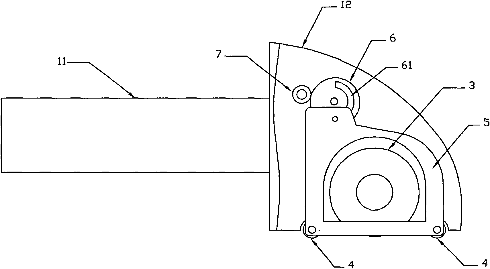
[0037] figure 1 Shown is the scab grinding machine of the present invention, comprising a handle 11, a housing 12 fixedly connected with the handle 11, a housing opening 13 is provided at the lower end of the housing 12; in the housing 12 A motor 2 is provided, a rotary knife 3 connected with the motor 2, and the rotary knife 3 is externally ground through the housing opening 13 (see image 3 shown);

[0038] It also includes an adjustment bracket 5, the adjustment bracket 5 includes rollers 4 respectively arranged on both sides of the housing opening 13 at the lower end of the housing 12, and an adjustment mechanism for adjusting the vertical movement of the rollers 4. In this embodiment Two adjustment plates 51 with pins are set in the example, and the adjustment plates 51 are vertically connected with the center line of the rotating roller 4 and are respectively located at the two ends of the rotating roller 4 (see figure 1 or figure 2 shown), and the bull gear 6 provid...

Embodiment 2

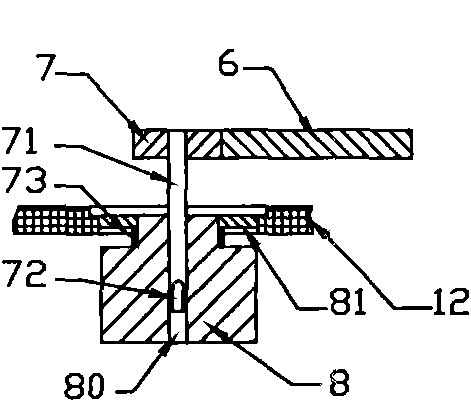
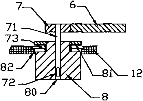
[0042] In this embodiment, on the basis of the above-mentioned embodiments, the adjustment mechanism in the above-mentioned embodiments is replaced by a T-shaped connecting bracket 52 fixedly connected to the rotating roller 4, and the horizontal branch 521 of the T-shaped connecting bracket 52 is horizontally fixed on two Between the rotating rollers 4, one end of the connecting plate 53 is hinged with the vertical branch 522 of the T-shaped connecting bracket 52, and the other end of the connecting plate 53 is hinged on the pin of the cam 54. Bull gear 6, described adjusting device is set as pinion 7 meshing with bull gear 6 in the present embodiment (see Figure 7 shown); in this embodiment, the pinion 7 is set to be connected with a locking device, and the locking device is fixedly connected with the pinion 7 coaxially with a first locking gear 81, and the first locking gear 81 is externally meshed with the second locking gear 82. The central axis of the second locking gea...


PUM


Abstract

The invention relates to a scab grinding machine, which comprises a handle and a shell fixedly connected with the handle, wherein a shell opening is arranged at the lower end of the shell, and a motor and a rotary cutter connected with the motor are arranged in the motor; and the rotary cutter grinds outwards through the shell opening. The scab grinding machine also comprises an adjusting support, wherein the adjusting support comprises rotary rollers arranged at the two sides of the shell opening at the lower end of the shell, and an adjusting mechanism capable of adjusting the rotary rollers to move up and down. When adjusting, the adjusting mechanism moves up and down instead of opening or closing the rotary rollers to move back and forth; and the scab grinding machine has accurate adjustment, reliable locking after adjusting and easy operation.

Description

technical field [0001] The invention relates to a medical device, in particular to a scab grinding machine. Background technique [0002] After extensive deep burns, the retention of necrotic tissue on the wound surface leads to extravasation of a large amount of body fluid and edema under the scab, leading to acute microcirculation disturbance, low immune function, endocrine disorder and visceral function damage. Therefore, the treatment of deep wounds, especially the treatment of deep second-degree wounds, has become the hot spot, focus and focus of current burn surgery research in the world, and it is also a worldwide problem that needs to be solved urgently. [0003] Burn wounds can be divided into I degree, II degree (shallow II degree, deep II degree) and III degree burn clinically; the necrotic tissue of wound is called scab. First-degree burns do not need to be treated; third-degree burn wounds must be repaired by escharectomy and skin grafting. However, this metho...

Claims


Application Information

Patent Timeline
Patent Type & Authority Applications(China)
IPC IPC(8): A61B17/00
Inventor 周洪春周青
Owner 周洪春
Why Eureka
Try Eureka