Lubricating oil regeneration device of waste internal-combustion engine

A regenerative device and internal combustion engine technology, applied in the direction of lubricating composition, molecular distillation, etc., can solve the problems of wasting resources, affecting cooling and lubrication effects, increasing enterprise costs, etc., and achieve the effects of reasonable structural design, large purification benefits and quality

Inactive Publication Date: 2010-07-14
王树波 +2
View PDF3 Cites 7 Cited by
  • Summary
  • Abstract
  • Description
  • Claims
  • Application Information

AI Technical Summary

Problems solved by technology

The quality control of lubricating oil in the use process is particularly important. Since the use process is inevitably "polluted" by mechanical high temperature, waste water, metal and other powder impurities, the waste oil that is replaced when it is off-line is burned as fuel oil and cannot be recycled. The first Waste of resources, the second increases the cost of the enterprise, and the third is when fuel oil is burned and pollutes the environment
[0003] Lubricating oil will inevitably be mixed with a small amount of water and mechanical impurities during the working process. These impurities will cause the viscosity of the lubricating oil to rise, emulsification, and affect the cooling and lubrication effects. The carbon chains of these polymer heavy oil components are continuous at high temperatures. It is easy to break, leading to symptoms such as lubrication failure, and new oil needs to be replaced immediately. At present, there is no research on the processing and regeneration of base oil in lubricating oil

Method used


Image

  • Lubricating oil regeneration device of waste internal-combustion engine
  • Lubricating oil regeneration device of waste internal-combustion engine
  • Lubricating oil regeneration device of waste internal-combustion engine

Examples


Embodiment 1

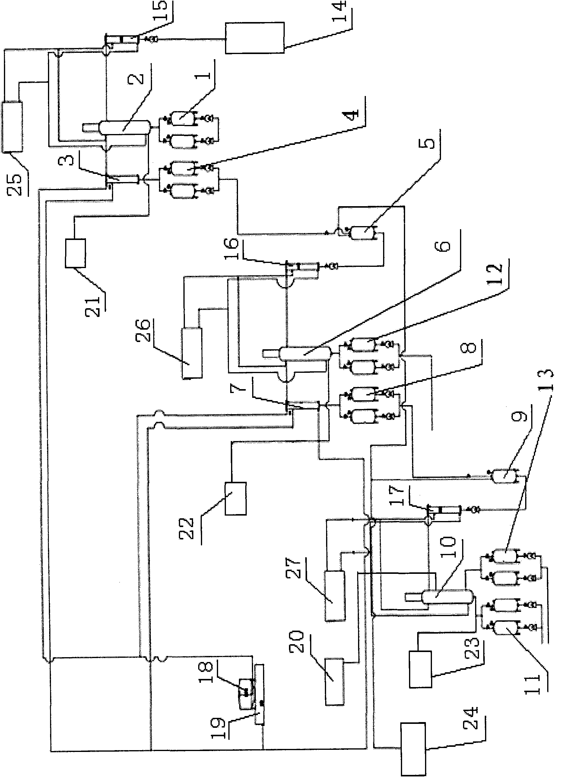
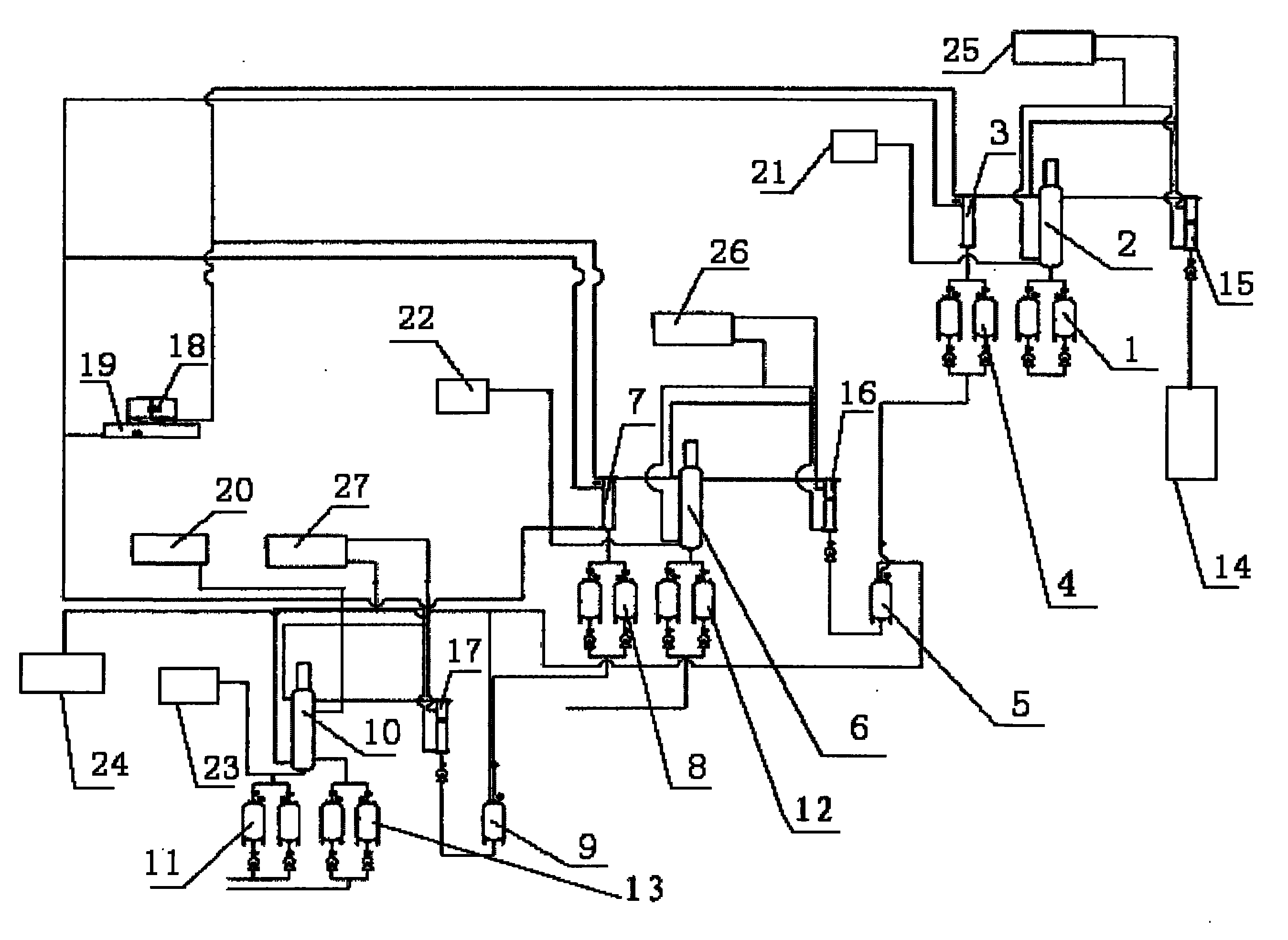
[0017] The waste internal combustion engine lubricating oil regeneration device of this example includes a raw material pretreatment tank 14 for separating free water in waste oil from oil products and removing free water. The primary heat exchanger 15, the primary heat exchanger 15 is connected with the primary distiller 2 for removing the emulsified water in the oil product, and the primary distiller 2 is connected with the primary cooler 3 for cooling the oil product And the primary waste oil tank 1 for collecting emulsified water, the primary cooler 3 is connected with the primary product oil tank 4, the primary product oil tank 4 is connected with the primary intermediate oil tank 5, and the primary intermediate oil tank 5 is connected with the The secondary heat exchanger 16 for reheating the oil product in it, the secondary heat exchanger 16 is connected with the secondary distiller 6 for removing the light component gasoline and diesel oil in the oil product, the second...


PUM


Abstract

The invention relates to a lubricating oil regeneration device of a waste internal-combustion engine, belonging to the technical field of regeneration device structures. The lubricating oil regeneration device comprises a pretreatment tank of raw materials; the pretreatment tank of the raw materials is connected with a first-stage heat exchanger which is connected with a first-stage distiller; the first-stage distiller is connected with a first-stage cooler and a first-stage waste oil tank; the firs-stage cooler is connected with a first-stage finished product oil tank which is connected with a first-stage intermediate oil tank which is connected with a second-stage heat exchanger; the second-stage heat exchanger is connected with a second-stage distiller which is connected with a second-stage cooler and a second-stage waste oil tank; the second-stage cooler is connected with a second-stage finished product oil tank which is connected with a second-stage intermediate tank; the second-stage intermediate tank is connected with a third-stage heat exchanger which is connected with a third-stage distiller; and the third-stage distiller is connected with a third-stage finished product oil tank and a third-stage waste oil tank. The invention has reasonable structural design and can thoroughly separate and purify light and heavy base oil components in the waste lubricating oil.

Description

technical field [0001] The invention relates to a regeneration device for lubricating oil of a waste internal combustion engine, which belongs to the technical field of regeneration device structures. Background technique [0002] Lubricating oil is widely used in transportation, manufacturing, rubber and plastics, chemical industry and other industries. With the growth of the national economy, its demand and consumption are also increasing. At present, the annual sales volume of lubricating oil in China has exceeded 5 million tons, and it is increasing every year. The rate of increase of more than 13% means that at least 4 million tons of waste lubricating oil are produced every year, and there is a trend of continued growth. The quality control of lubricating oil in the use process is particularly important. Since the use process is inevitably "polluted" by mechanical high temperature, waste water, metal and other powder impurities, the waste oil that is replaced when it i...

Claims


Application Information

Patent Timeline
Patent Type & Authority Applications(China)
IPC IPC(8): C10M175/00C10M175/02B01D3/12
Inventor 董海生吴斌王树波
Owner 王树波
Why Eureka
Try Eureka