Static-pressure horizontal electroplating bath

An electroplating tank and horizontal technology, applied in the plating tank and other directions, can solve the problems of reducing the working stability of the plating tank, short-circuit burns, large strip alignment deviation, etc., to improve the exhaust capacity and electroplating efficiency, high two-way horizontal injection , the effect of reducing the height

Active Publication Date: 2010-07-14
北京中冶设备研究设计总院有限公司
View PDF4 Cites 6 Cited by
  • Summary
  • Abstract
  • Description
  • Claims
  • Application Information

AI Technical Summary

Problems solved by technology

2. The transverse uniformity of the steel strip coating mainly depends on the value of E. The value of E is essentially the distance between cathode and anode h o The variation range, the E value is large, h o The range of variation is large, and the uniformity of the coating is not good
3. Affected by many factors, the values ​​of E and ΔS are often difficult to determine accurately, so the h determined during the design of the plating tank o value, it is often difficult to satisfy h o >(0.5E+ΔS), in this case, short-circuit burns sometimes occur, thereby reducing the working stability of the plating tank
However, the LCC-H tank still has the problem of short-circuit burns between the anode and the strip steel in production, which shows that its ability to control the running position of the strip steel cannot fully meet the production requirements; in addition, the current efficiency of the LCC-H tank is also low , large deviation of strip centering and complex structure, etc.

Method used


Image

  • Static-pressure horizontal electroplating bath
  • Static-pressure horizontal electroplating bath
  • Static-pressure horizontal electroplating bath

Examples


Embodiment Construction

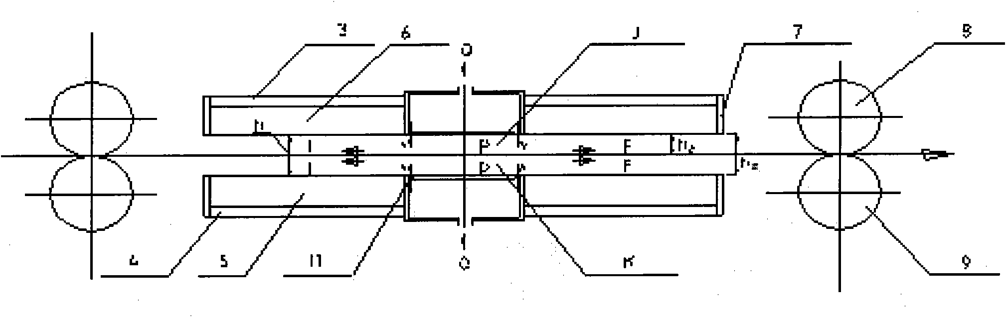
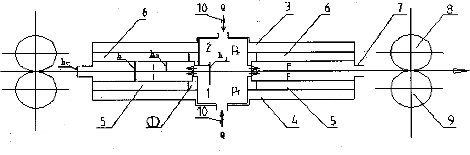
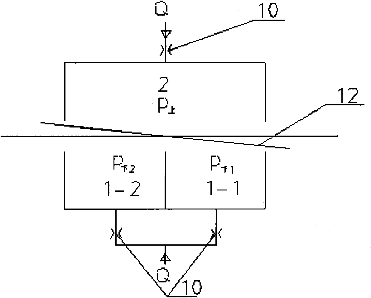
[0049] Embodiments of the present invention are described in further detail below in conjunction with the accompanying drawings: Figure 2 ~ Figure 4 The static pressure horizontal electroplating tank shown mainly includes the upper frame 3, the lower frame 4, the lower anode 5, the upper anode 6, the liquid baffle 7, the conductive roller 8, the supporting roller 9, the edge cover and the automatic tracking system and other main parts , between the electroplating areas I and F in the middle of the electroplating tank, a double-chamber lower static pressure chamber 1 and an upper static pressure chamber 2 are arranged; the upper static pressure chamber 2 is located in the middle of the upper frame 3, and the double-chamber lower static pressure chamber 1 is located in In the middle part of the lower frame 4, the upper and lower static pressure chambers are of rectangular box structure, and the material is carbon steel rubber lining; the static pressure chamber head ① made of gl...


PUM


Abstract

The invention provides a static-pressure horizontal electroplating bath, which consists of an upper frame, a lower frame, a lower anode, an upper anode, liquid blocking plates, a conductive roller, a supporting roller, an edge cap and an automatic tracking system, and is characterized in that: a double-cavity lower static-pressure cavity and an upper static-pressure cavity are formed between electroplating regions I and F in the middle of the electroplating bath; and plating solution is input into the upper and lower static-pressure cavities and horizontally sprayed into the electroplating regions I and F through a gap between band steel and a cavity head of the upper static-pressure cavity and a gap between the band steel and a cavity head of the lower static-pressure cavity. The gap between the band steel and the cavity head of the static-pressure cavity is smaller than the distance between the band steel and the anode; the transverse width of a main cavity of the static-pressure cavity is slightly smaller than the width of the band steel; and the distance between the upper and lower liquid blocking plates is smaller than the anode distance. High liquid static-pressure band steel clamping capacity and liquid static-pressure anti-band steel deflection capacity are established in the bath, so bidirectional horizontal injection of the plating solution in the middle of the bath is realized, and short circuit and burning problems of the band steel and the anode in a horizontal electroplating bath are solved. The static-pressure horizontal electroplating bath has the advantages of stable and reliable running, high coating quality, high current density, low power consumption, simple and compact device structure and the like.

Description

Technical field: [0001] The invention relates to the technical field of continuous electroplating of steel strips, in particular to a horizontal electroplating tank in the technical field of continuous electroplating of steel strips. Background technique: [0002] The electroplating tank is the core equipment in the strip continuous electroplating production line, and it is the main factor that determines the electroplating efficiency, product quality and production cost. The main signs of an electroplating tank with excellent performance are: high current density, good coating quality, low power consumption, good working stability, and simple and compact equipment. When the electroplating solution and electroplating process are constant, the main factors affecting the performance of the plating tank are: the height E of the running space of the strip steel in the tank, the centering deviation ΔS and the distance h between the anode and the strip steel o ; The exhaust capac...

Claims


Application Information

Patent Timeline
Patent Type & Authority Applications(China)
IPC IPC(8): C25D17/02C25D7/06
Inventor 翁祺于平高斌郭小平王德祥
Owner 北京中冶设备研究设计总院有限公司
Why Eureka
Try Eureka