Tamping device with independent hydraulic shock excitation and clamping movement

A vibration-exciting and hydraulic technology, which is applied to roads, tracks, ballast layers, etc., can solve the problems of destroying the working environment of the hydraulic system of the tamping device, and achieve the effects of increasing life, protecting stability, and improving the working environment

Inactive Publication Date: 2010-07-14
ZHEJIANG UNIV +1
View PDF0 Cites 11 Cited by
  • Summary
  • Abstract
  • Description
  • Claims
  • Application Information

AI Technical Summary

Problems solved by technology

In this way, the clamping hydraulic cylinder on the tamping arm will vibrate accordingly, and the tamping box and even the tamping vehicle itself will vibrate

Method used


Image

  • Tamping device with independent hydraulic shock excitation and clamping movement
  • Tamping device with independent hydraulic shock excitation and clamping movement
  • Tamping device with independent hydraulic shock excitation and clamping movement

Examples


Embodiment Construction

[0021] The present invention will be further described below in conjunction with drawings and embodiments.

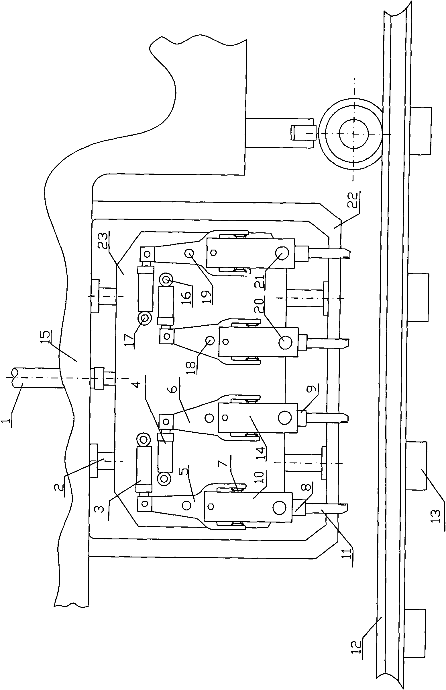
[0022] Figure 1 to Figure 7 An embodiment of the present invention is shown, and the excitation hydraulic cylinder in this embodiment is a double-rod hydraulic cylinder.

[0023] Such as figure 1 As shown, the tamping device is fixed on the frame 22 of the tamping trolley 15 . The tamping device comprises a tamping box body 23 capable of lower insertion movement, an inner tamping head and an outer tamping head installed oppositely on the two sides of the tamping box body 23 . The lower insertion movement of the tamping box 23 is realized by the lifting hydraulic cylinder 1 on the tamping trolley 15. In order to prevent twisting and deflection during the lower insertion of the tamping box 23, two vertical guides are installed on the tamping trolley frame 22. Column 2, these two guide columns have also ensured the lower insertion depth of tamping box 23.

[0024] Suc...


PUM


Abstract

The invention discloses a tamping device with independent hydraulic shock excitation and clamping movement. Tamping heads are correspondingly arranged on two side surfaces of a tamping box body of the tamping device, the tamping heads on each side surface are matched in pairs, each pair of tamping heads comprises an inner tamping head and an outer tamping head, a cylinder body of a clamping hydraulic cylinder of each tamping head is hinged with the tamping box body, the upper end of an upper tamping arm is hinged with piston rods of the clamping hydraulic cylinder, the upper tamping arm is also hinged with a supporting shaft fixed on the tamping box body, piston rods of a shock excitation hydraulic cylinder are fixedly connected with the lower end of the upper tamping arm, cylinder bodies are fixedly connected with shifting forks, the upper tamping arm is fixedly connected with a connecting element, a lower tamping arm is hinged with the supporting shaft fixed on the connecting element, pin shafts are fixed to the upper end of the lower tamping arm, the supporting shaft arranged on the tamping box body, the supporting shaft arranged on the connecting element and the pin shafts are all vertical to the side surface of the tamping box body, the pin shafts are placed in fork grooves of the shifting forks, tamping picks are fixed to the lower end of the lower tamping arm, and the clamping hydraulic cylinder of the inner tamping head and the outer tamping head in each pair of tamping heads is arranged between the upper tamping arms of the inner tamping head and the lower tamping head.

Description

technical field [0001] The invention relates to the technical field of railway tamping devices, in particular to a tamping device with independent hydraulic vibration and clamping movement. Background technique [0002] The tamping device is a track maintenance machine specially used for tamping railway track ballast. Compared with traditional electric tamping machines and small hydraulic tamping machines, the tamping device has many advantages such as safe, stable, fast and low labor intensity. At present, the tamping device has achieved diversified structural forms, unique excitation methods, and high operating efficiency, and has been widely used in domestic line maintenance operations, showing unique advantages. With the vigorous development of my country's railway construction and social progress, tamping devices will inevitably become the mainstream. [0003] The operation characteristics of the tamping device require that the tamping device must realize the clamping...

Claims


Application Information

Patent Timeline
IPC IPC(8): E01B27/20
Inventor 龚国芳杨林勇刘国斌刘学海闵超庆杨文志刘毅杨华勇
Owner ZHEJIANG UNIV
Why Eureka
Try Eureka