Optical imaging alignment measurement device

A measuring device and optical imaging technology, which is applied in the direction of measuring point marking, etc., can solve problems in the field of missile artillery launch, such as difficulties in launching missiles, accuracy, reliability limitations, and expensive measuring instruments, and achieve easy installation and application, high centering accuracy, The effect of strong reflection

Inactive Publication Date: 2010-07-14
CHANGCHUN INST OF OPTICS FINE MECHANICS & PHYSICS CHINESE ACAD OF SCI
View PDF0 Cites 7 Cited by
  • Summary
  • Abstract
  • Description
  • Claims
  • Application Information

AI Technical Summary

Problems solved by technology

[0003] Usually, the method used to determine the relative position of two objects is to use a high-precision theodolite to measure the fixed cooperative targets on the two objects respectively, but the measuring instruments used in this measurement method are expensive, have high requirements for use, and are easily damaged. Poor mobility, it is very difficult to apply in the field of missile artillery launch
Other measurement methods have relatively large limitations in terms of accuracy and reliability.

Method used


Image

  • Optical imaging alignment measurement device
  • Optical imaging alignment measurement device
  • Optical imaging alignment measurement device

Examples


Embodiment Construction

[0018] The present invention will be described in further detail below in conjunction with the accompanying drawings and specific embodiments.

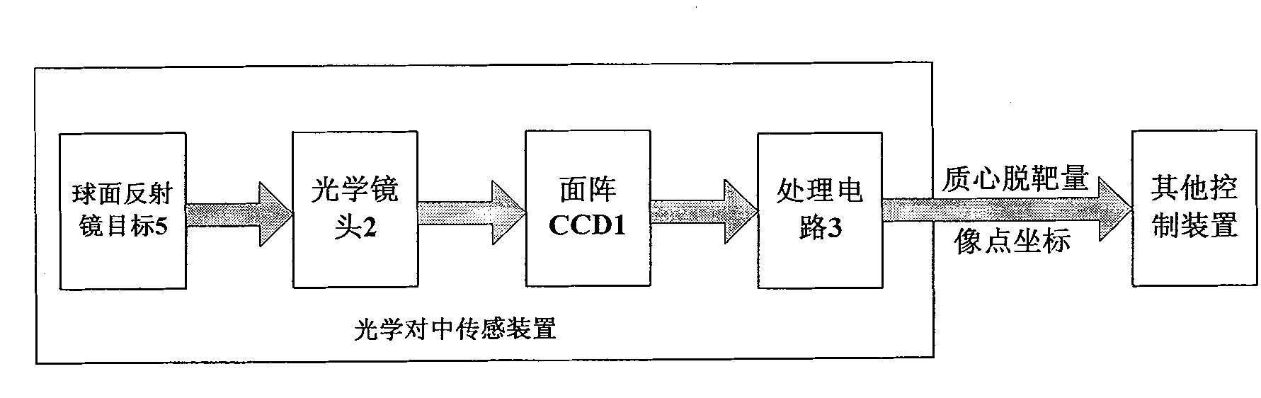
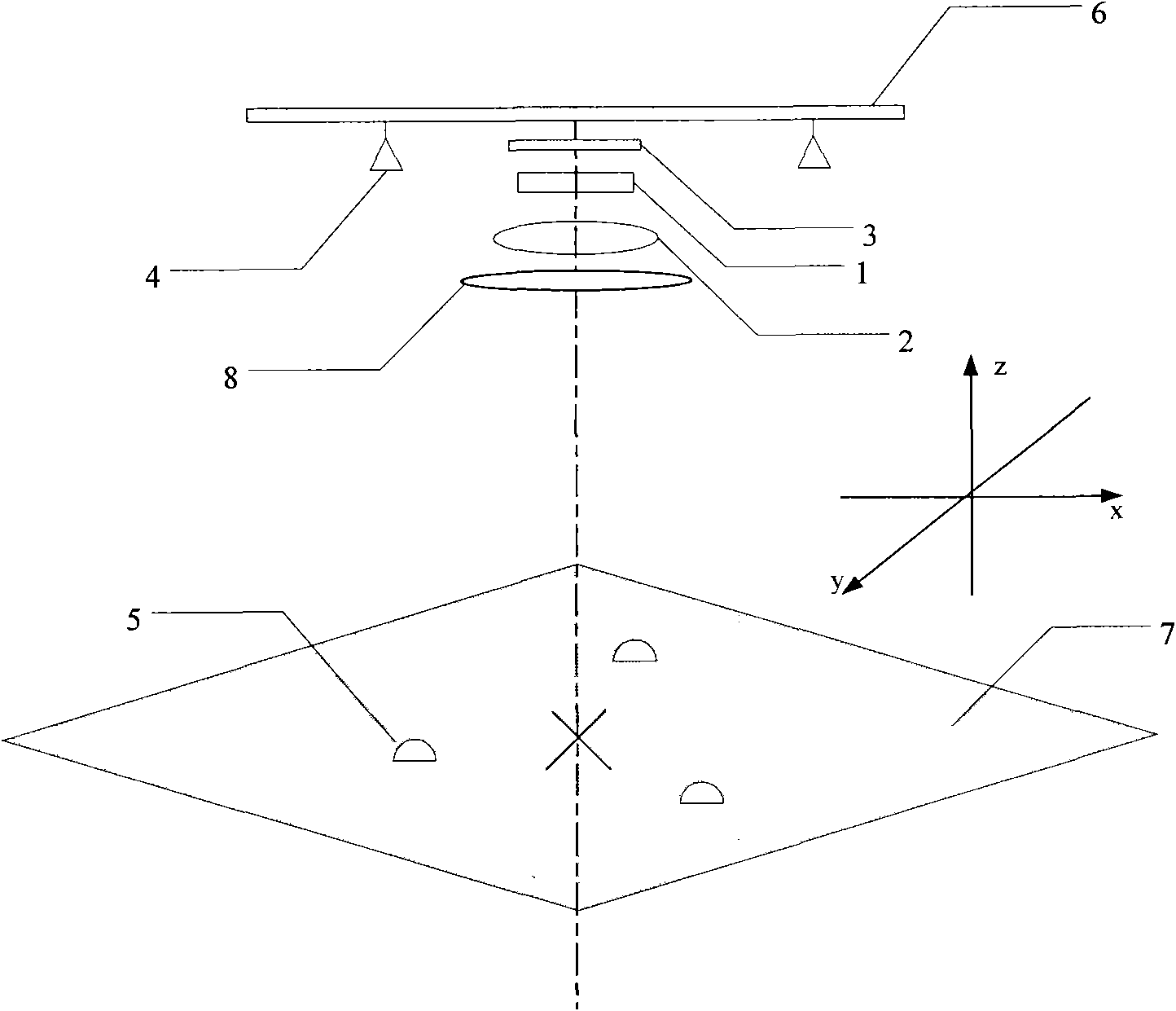
[0019] The system adopted by this measurement device includes: area array CCD1, optical lens 2, video processing circuit 3, LED red light source 4, spherical reflector 5, plane 6, non-reflective plane 7, (such as figure 2 shown).

[0020] The optical lens 2 can ensure that the image of the spherical mirror 5 can be imaged on the target surface of the area array CCD1.

[0021] The processing circuit 3 processes the image digital signal in real time, and completes the acquisition, processing and output of the image data of the area array CCD1.

[0022] Measurement method and working process:

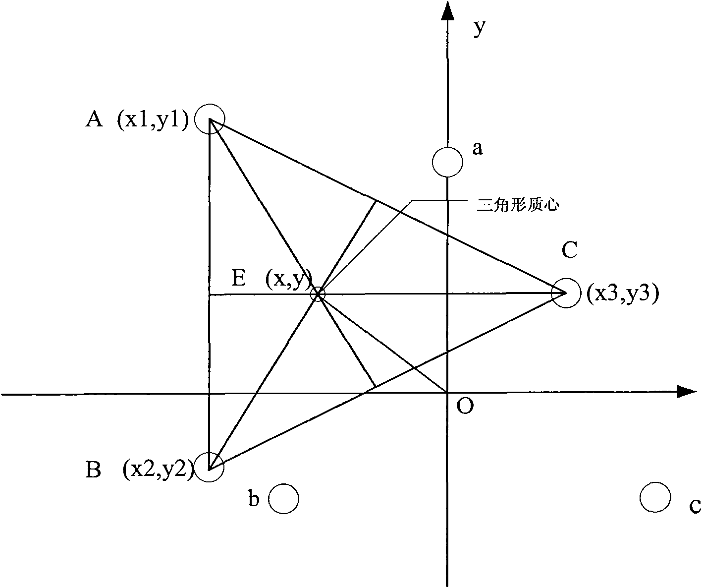
[0023] as attached figure 2 , use red light source 4 to illuminate three spherical reflectors 5, the centroids of the three spherical reflectors are the center of the plane, and through the imaging of the reflectors by the camera, the amount ...


PUM


Abstract

The invention relates to an optical imaging alignment measurement device, which can carry out high-precision determination on relative positions of two objects. The device comprises an area array CCD, an optical lens, a video processing circuit, an LED red light source and spherical reflectors. The position and the connection relation of each part are that the area array CCD, the optical lens, the video processing circuit and the LED red light source are arranged on a plane; the three high-reflectivity spherical reflectors are arranged on another plane; the red light source is used to illuminate the three spherical reflectors; the mass center of the three reflectors is the center of the plane; and the alignment of the two planes is completed by processing the imaging of a camera to the reflector, calculating a miss distance of the mass center and coordinates of images of the three reflectors by the video processing circuit, sending the numerical values to a control device, controlling the plane of the camera to move along the X, Y and Z directions to make the mass center and the center of the CCD target plane coincident, and moving the centers of three target image points to the predetermined CCD target plane coordinate. The measurement device is simple, and has high alignment precision, small volume and easy installation and application.

Description

technical field [0001] The invention relates to an optical imaging centering measuring device, which can determine the relative positions of two objects with high precision. Background technique [0002] In the field of missile artillery launching, the launching vehicle and the loading vehicle need to enter a fixed relative position, so a fast and accurate measuring device is required. [0003] Usually, the method used to determine the relative position of two objects is to use a high-precision theodolite to measure the fixed cooperative targets on the two objects respectively, but the measuring instruments used in this measurement method are expensive, have high requirements for use, and are easily damaged. The mobility is poor, and it is very difficult to apply it in the field of missile artillery launch. Other measurement methods have relatively large limitations in terms of accuracy and reliability. [0004] This invention is an alignment measurement device with low pr...

Claims


Application Information

Patent Timeline
Patent Type & Authority Applications(China)
IPC IPC(8): G01C15/02
Inventor 耿天文李建荣刘畅赵雁刘绍锦沈铖武李冬宁刘兆荣
Owner CHANGCHUN INST OF OPTICS FINE MECHANICS & PHYSICS CHINESE ACAD OF SCI
Why Eureka
Try Eureka