Offshore oil platform floating ice speed in-situ monitoring device

A monitoring device, offshore oil technology, applied in the direction of using a device measuring the time required to move a certain distance, position/direction control, radio wave measurement system, etc., can solve image sequence analysis errors, displacement measurement deviations, increase or decrease 0.29 meters and other problems, to achieve the effect of improving reliability and ensuring accuracy

Inactive Publication Date: 2010-07-14
CHINA NAT OFFSHORE OIL CORP +1
View PDF0 Cites 8 Cited by
  • Summary
  • Abstract
  • Description
  • Claims
  • Application Information

AI Technical Summary

Problems solved by technology

However, due to the low spatial resolution of images obtained by satellite and aerial remote sensing, only information on changes in large-scale ice regions can be obtained, and it is impossible to obtain accurate velocity data of sea ice floes, especially ice floes with a surface area of ​​less than 1 square meter. In addition, the monitoring method of satellite remote sensing and aerial photography is limited by its orbit or flight time period, and it is difficult to obtain continuous and complete sea ice movement data
Although video monitoring systems can be installed on offshore oil platforms to observe the flow velocity of ice floes, these devices are all fixed on the structure of the oil platform at one time, and changes in the ocean tidal water level cause the imaging distance to change, resulting in the imaging visual If the field range changes, it will bring a large error in the image sequence analysis process. For example, for a camera with a field of view angle of 60, the set field of view radius is 1 meter, and when the tidal drop is 0.5 meters, its field of view The field range will increase or decrease by 0.29 meters, which will cause displacement measurement deviations for the displacement calculation of the ice floes based on different image sequences, resulting in large errors in the analysis of long-sequence and continuous ice floes movement speed data.

Method used


Image

  • Offshore oil platform floating ice speed in-situ monitoring device
  • Offshore oil platform floating ice speed in-situ monitoring device
  • Offshore oil platform floating ice speed in-situ monitoring device

Examples


Embodiment Construction

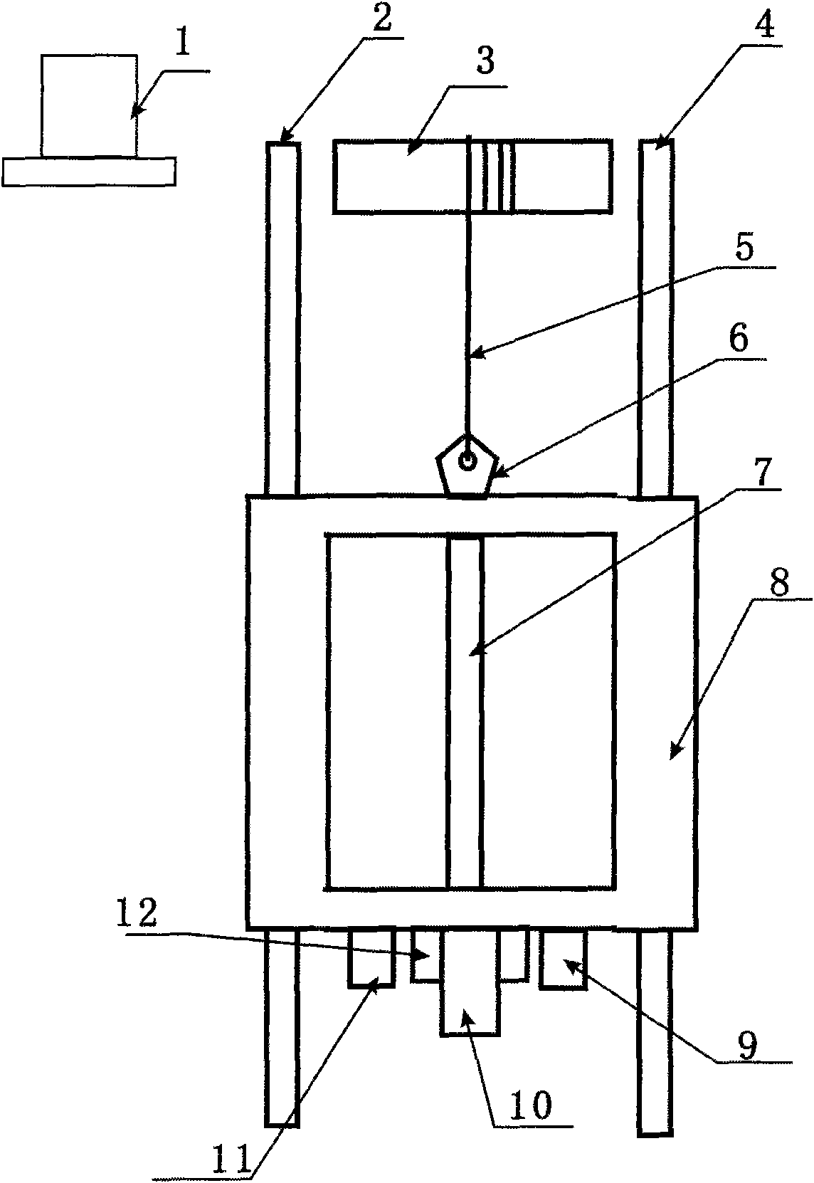
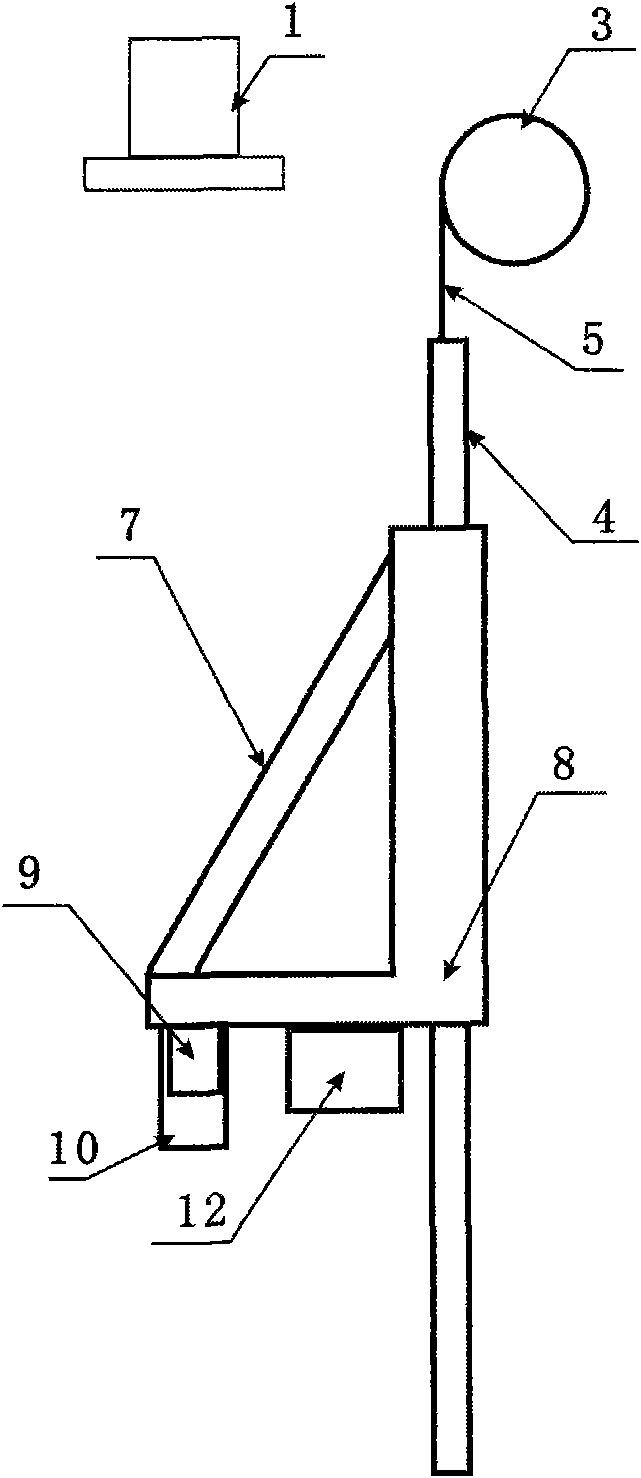
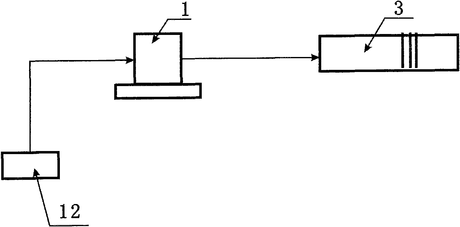
[0034] The invention discloses a device for automatically adjusting the position of a sea ice imaging monitoring platform arranged on an offshore oil platform. The image monitoring platform moves up and down along two circular guide rods, and the two circular guide rods are fixed on the edge of the offshore oil platform. The distance moved by the sea ice image monitoring platform is determined by the cable controller according to the sea surface water level from the acoustic water level gauge. The information is automatically controlled to ensure that the field of view and imaging distance of the acquired images are not affected by tidal changes.

[0035] The acoustic water level gauge uses the sound tube to send out the sound signal, so that the sound wave propagates in the air. When encountering the water surface, the sound wave will be reflected on the surface of two different media. By calculating the time spent on the propagation and echo sound wave, we can know The dista...


PUM


Abstract

The invention discloses an offshore oil platform floating ice speed in-situ monitoring device which comprises a sea ice imaging platform and an imaging distance automatic adjusting device and further comprises an acoustic water level gauge, a wire arrangement controller, a wire arranging device and guide rods. The in-situ sea ice monitoring device is installed on an offshore oil platform. The device further comprises an offshore monitoring platform and a cable; the wire arrangement controller is connected with the acoustic water level gauge and receives the offshore level change information from the acoustic water level gauge, and the wire arrangement controller is connected with the wire arranging device and used for controlling the number of rotating turns of the wire arranging device to regulate the distance between the sea ice imaging platform and a water surface; and the sea ice imaging platform is penetrated through the two guide rods through sliding holes to enable the sea ice imaging platform to slide up and down in the vertical direction relative to the guide rods. The in-situ monitoring device of the invention can automatically regulate the imaging distance of an imaging device along with tidal levels to reduce the error influence brought by the change of the tidal levels and improve the accuracy of floating ice displacement measurement.

Description

technical field [0001] The invention relates to an in-situ visual monitoring device for the sea surface, in particular to an in-situ monitoring device for floating ice velocity on an offshore oil platform based on image sensing technology. Background technique [0002] Sea ice is one of the main products in high-latitude seas in winter. A large amount of sea ice covering the sea drifts with the tide and sea wind, impacting offshore drilling platforms and ships, causing sea ice disasters such as the collapse of offshore drilling platforms and interruption of shipping. The latitude of the northern waters of my country is relatively high, and a large amount of sea ice is produced every winter. Therefore, how to accurately monitor changes in ice conditions, so as to release early warning information and emergency measures for operations in a timely manner, has become an urgent problem to be solved in the safe production of high-latitude offshore drilling platforms. major problem....

Claims


Application Information

Patent Timeline
Patent Type & Authority Applications(China)
IPC IPC(8): G01P3/68G05D3/00
Inventor 兰志刚于新生靳卫卫张丰丽宋积文李辉辉
Owner CHINA NAT OFFSHORE OIL CORP
Why Eureka
Try Eureka