Lossy compression method for multifocal multiphoton microscopic imaging data

A multiphoton microscope and imaging data technology, which is applied in image communication, digital video signal modification, television, etc., can solve the problem of huge amount of microscopic image data

Inactive Publication Date: 2010-07-14
HANGZHOU DIANZI UNIV
View PDF0 Cites 3 Cited by
  • Summary
  • Abstract
  • Description
  • Claims
  • Application Information

AI Technical Summary

Problems solved by technology

However, this development has also caused the amount of microscopic image data to be imaged to become larger and larger

Method used


Image

  • Lossy compression method for multifocal multiphoton microscopic imaging data
  • Lossy compression method for multifocal multiphoton microscopic imaging data
  • Lossy compression method for multifocal multiphoton microscopic imaging data

Examples


Embodiment Construction

[0030] The lossy compression method of multi-focus multi-photon microscope imaging data adopts the following specific implementation steps on the MATLAB6.5 programming platform:

[0031] Step (1) Use the fopen() function to open, and the fread() function to read the binary format data file gfp_106000.int of the multi-focus multiphoton microscope imaging, so that the resolution of the binary format data file is 192×192, and each pixel is 8-bit, 30-layer image.

[0032] The binary format data file forms a 30-layer image matrix with a resolution of 192×192, which is stored in the three-dimensional matrix img (that is, the layered imaging image formed by the imaging data block, whose size is 192×192×30, and the element value range 0 to 255).

[0033] Step (2) extracts the first layer data of the three-dimensional matrix img as the input f(x, y) used for compression (i.e. f(x, y)=img(:,:,1)), and adopts the JPEG algorithm to process f( x, y) to compress, the specific steps are as...


PUM


Abstract

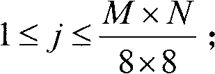
The invention relates to a lossy compression method for multifocal multiphoton microscopic imaging data. The existing data compression effects are not good. The method of the invention comprises the following steps: extracting binary format imaging data from an imaging data file and carrying out lossy compression on the extracted image data by a JPEG algorithm. The extracted binary format data file forms an image matrix; any layer of the image matrix is compressed by the JPEG algorithm; firstly, the image of the layer is divided into nonoverlapping 8*8 subimages; then the subimages are coded by carrying out grey level moving, forward discrete cosine transformation, normalization, quantization and Huffman coding on the subimages; and finally, all the subimages of the layer are coded by the method. The invention takes example by the characteristic of a JPEG coding standard that the information which has less effect on the image quality is neglected, carries out lossy compression on a multifocal multiphoton microscopic imaging image data block, and obtains considerable compressibility.

Description

technical field [0001] The invention belongs to the field of multi-focus multi-photon microscope imaging, and relates to a lossy compression method for multi-focus multi-photon microscope imaging data. Background technique [0002] Multifocal multiphoton microscopy is one of the most effective three-dimensional imaging techniques for biological tissues in the world today. This technology uses laser light as the light source on the basis of traditional fluorescence microscope imaging, and installs a laser scanning device. It uses near-infrared laser light to converge at the focal point to achieve multi-photon fluorescence excitation. At the same time, it uses multi-photon excitation to reduce light damage and Photobleaching, and then obtain high-resolution fluorescent images of the fine structure inside cells or tissues, and use computer image processing technology to enable researchers to observe the fine structure and morphological changes inside cells or tissues. At prese...

Claims


Application Information

Patent Timeline
Patent Type & Authority Applications(China)
IPC IPC(8): H04N7/26H04N7/30H04N19/119H04N19/62
Inventor 王瑞荣薛安克王建中邹洪波何峰
Owner HANGZHOU DIANZI UNIV
Why Eureka
Try Eureka