Pneumatic rotary air plasma jet source

An air plasma and plasma technology, which is applied in the field of ion jet sources, can solve problems such as difficulty in realizing the surface treatment process of air plasma jets, and achieve the effects of improving energy efficiency, reducing costs, and simplifying structure

Active Publication Date: 2010-07-14
WUHU GUOFENG PLASTIC TECH +1
View PDF0 Cites 18 Cited by
  • Summary
  • Abstract
  • Description
  • Claims
  • Application Information

AI Technical Summary

Problems solved by technology

[0013] The purpose of the present invention is to provide a pneumatic rotating air plasma jet source, which can make the plasma form a rotating plasma jet by rotating the outer electrode outer cylinder and the nozzle, so as to solve the problem that the existing equipment is difficult to realize the air plasma jet surface treatment process

Method used


Image

  • Pneumatic rotary air plasma jet source
  • Pneumatic rotary air plasma jet source

Examples


Embodiment Construction

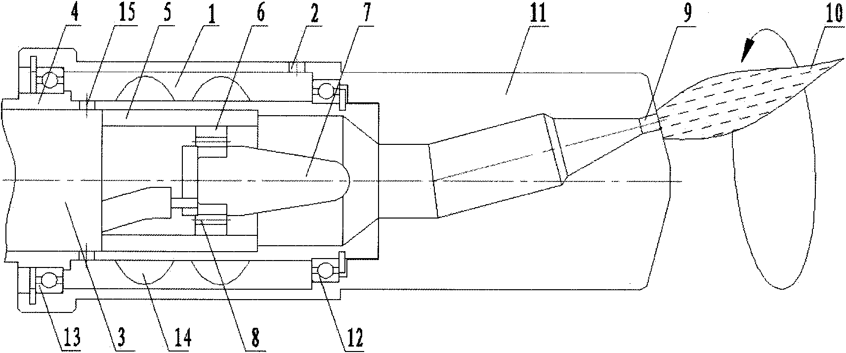
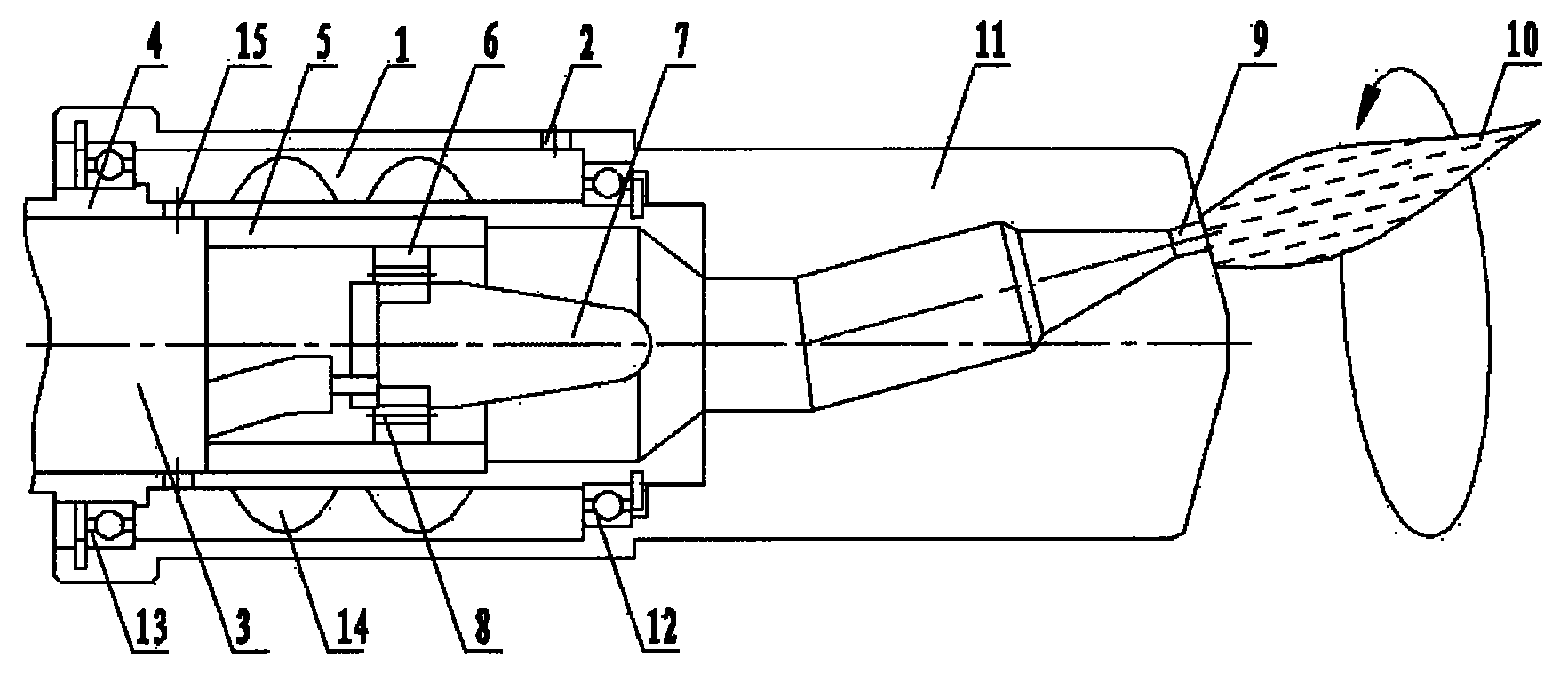
[0025] Such as figure 1 As shown, the pneumatic rotating air plasma jet source includes an inner electrode 7 , an air supply ring 6 , an insulating ring 5 , an outer electrode inner cylinder 4 , an outer electrode outer cylinder 11 , and bearings 12 and 13 . The rear part of the outer electrode inner cylinder 4 is the gas chamber 3, and a part of the gas in the gas chamber 3 enters the inner electrode 7 and the outer electrode inner cylinder 4 through the air channel 8 of the gas supply ring 6, and the passage at the front of the outer electrode outer cylinder, through The nozzle 9 flows out to provide a discharge to eject the plasma jet 10; since the axis of the nozzle 9 forms an included angle with the axis of the inner electrode 7, the plasma jet 10 ejected by the discharge deviates from the axis of the inner electrode. The other part of the gas in the gas chamber 3 enters the pneumatic rotating chamber 14 through the through hole 15 on the inner cylinder 4 of the outer ele...


PUM


Abstract

The invention discloses a pneumatic rotary air plasma jet source, which comprises an outer electrode outer barrel and an outer electrode inner barrel. A pneumatic rotary cavity is formed in the outer electrode outer barrel; the front of the outer electrode outer barrel is provided with a nozzle cavity of a nozzle; an air chamber is isolated at the back of the inner cavity of the outer electrode outer barrel; an air supply ring is arranged in the outer electrode inner barrel; an inner electrode is arranged in the air supply ring; and the outer electrode inner barrel is arranged in the pneumatic rotary cavity inside the outer electrode outer barrel and can be rotated relatively to the outer electrode outer barrel. By rotating the outer electrode outer barrel and the nozzle, plasmas can form rotary ion jet.

Description

technical field [0001] The invention relates to the field of plasma applications, in particular to a novel air plasma jet source, in particular to a pneumatic rotating air plasma jet source. Background technique [0002] In the automobile manufacturing process, the surface treatment technology of plastics has been indispensable as one of the important processes to ensure the appearance quality of products. As the trend of replacing steel with plastic continues to deepen, in the automobile manufacturing industry, almost all automobile bumpers are made of plastic materials. However, the surface treatment technology of plastic automobile bumpers cannot meet the development requirements of automobile technology. Therefore, a surface treatment technology that can be processed online, has good treatment effect, low cost, energy saving and environmental protection, and strong monitorability has a broad market. [0003] Usually, before being sprayed, flocked or bonded, the interio...

Claims


Application Information

Patent Timeline
IPC IPC(8): H05H1/26B08B7/00
Inventor 张文龙任兆杏黄娟孟令松孙辉陈辉任炟常陈洁陶胜银
Owner WUHU GUOFENG PLASTIC TECH
Why Eureka
Try Eureka