Exhaust pipe connection structure and exhaust pipe connection method

A technology of connection structure and connection method, which is applied in the direction of non-detachable pipe connection, pipe/pipe joint/pipe fitting, exhaust device, etc., can solve the problems of time-consuming processing and non-optimal welding, and achieve the effect of improving shape accuracy.

Inactive Publication Date: 2010-07-14
FUTABA IND CO LTD
View PDF1 Cites 22 Cited by
  • Summary
  • Abstract
  • Description
  • Claims
  • Application Information

AI Technical Summary

Problems solved by technology

The problem is that it takes time to process
The problem is that welding is not preferred in view of the working environment

Method used


Image

  • Exhaust pipe connection structure and exhaust pipe connection method
  • Exhaust pipe connection structure and exhaust pipe connection method
  • Exhaust pipe connection structure and exhaust pipe connection method

Examples


Embodiment Construction

[0038] Next, the best mode for carrying out the present invention will be described in more detail based on the accompanying drawings.

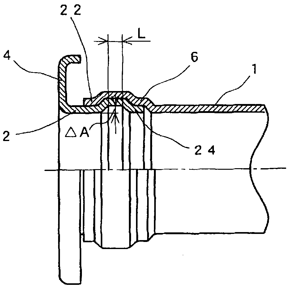
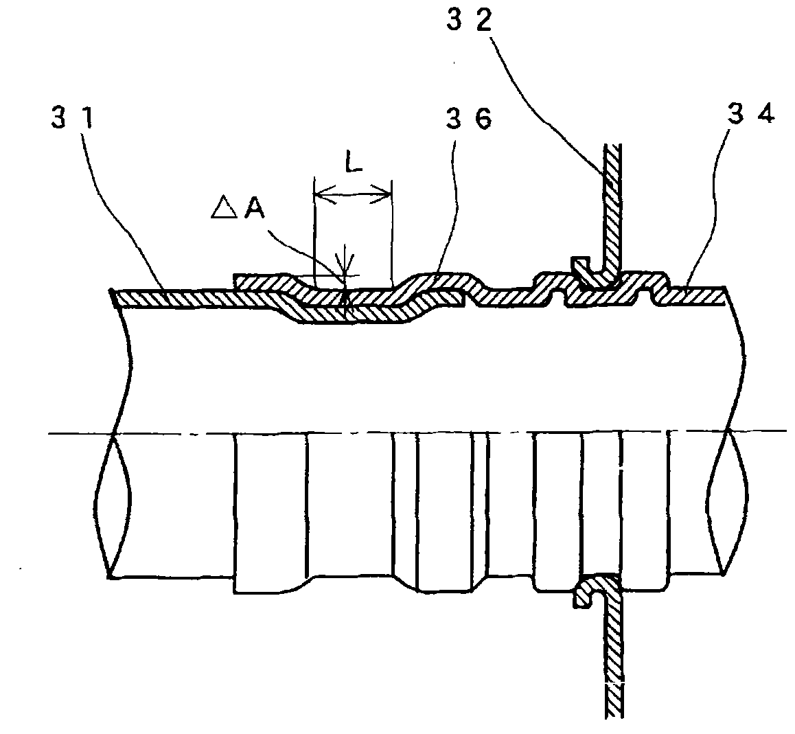
[0039] Such as figure 1 As shown, numeral 1 denotes an exhaust pipe, and a connecting pipe 2 is inserted into the exhaust pipe 1 for mutual connection. The flange 4 is integrally formed in advance on one end side of the connecting pipe 2 by, for example, press working. Also, an enlarged diameter portion 6 is preliminarily formed at one end of the exhaust pipe 1 so that the connection pipe 2 can be inserted thereinto. The outer periphery of the connecting pipe 2 is inserted into the inner periphery of the enlarged diameter portion 6, and the portion where the enlarged diameter portion 6 and the connecting pipe 2 overlap each other is radially molded for mutual connection.

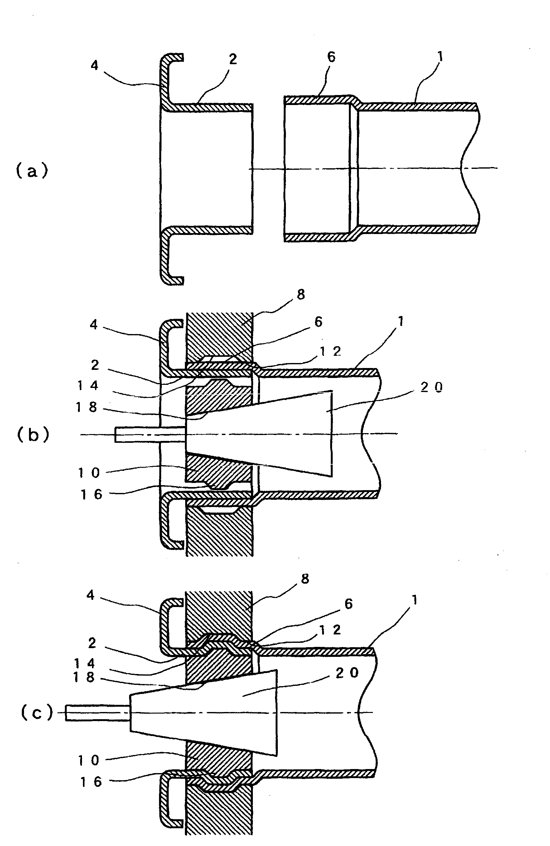
[0040] Next, refer to figure 2 Connection methods are described in process order. Such as figure 2 As shown in (a), the enlarged diameter portion 6 is formed in advan...


PUM


Abstract

An exhaust pipe connection structure for interconnecting a connection pipe and an exhaust pipe that are arranged in an exhaust system of an internal combustion engine. Either of the connection pipe and the exhaust pipe is inserted into the other, and the portion where the connection pipe and the exhaust pipe overlap each other is radially deformed for staking.

Description

technical field [0001] The present invention relates to an exhaust pipe connection structure and an exhaust pipe connection method for interconnecting an exhaust pipe and a connecting pipe arranged in an exhaust system of an internal combustion engine. Background technique [0002] Generally, in an exhaust system of an internal combustion engine, an exhaust manifold, a converter, and a muffler are arranged in a direction of exhaust gas flow and are each connected by an exhaust pipe. Each of the exhaust pipe and the converter, and the exhaust pipe and the muffler are connected by welding. [0003] However, welded connections are prone to stress concentration at the welded location. In order to have sufficient strength at the welded portion, it is necessary to provide the exhaust pipe with sufficient plate thickness. Accordingly, the problem of reducing the weight arises. Also, in order to stop exhaust leakage, the entire perimeter of the exhaust pipe must be welded. There...

Claims


Application Information

Patent Timeline
Patent Type & Authority Applications(China)
IPC IPC(8): F01N7/18F01N7/08F01N13/18F01N13/08
CPCF01N2450/20F01N13/08F01N13/1805B21D39/04B23P11/005F01N13/185F16L13/141F16L13/147F16L2013/145Y10T29/4994
Inventor 田中芳树大野一成须藤雅行佐藤文彦中泽哲夫
Owner FUTABA IND CO LTD
Why Eureka
Try Eureka