Cyclonic water filtration dust collecting device

A dust collection device and water filtration technology, which is applied in the direction of suction filter, etc., can solve the problems of unsatisfactory water-air contact mixing effect, prolonging the residence time of airflow, and poor dust removal effect, achieving compact structure, prolonging residence time, and good dust removal effect of effect

Inactive Publication Date: 2010-07-21
胡海荣
View PDF3 Cites 15 Cited by
  • Summary
  • Abstract
  • Description
  • Claims
  • Application Information

AI Technical Summary

Problems solved by technology

[0006] These patents are like the vacuum cleaners described above, which have the disadvantages of large volume and unsatisfactory contact and mixing effect of water and air, so there are inevitably disadvantages of poor dust removal effect
[0007] For this reason, the inventor has applied for a cyclone type water filter and dust collection device in the Chinese patent application number 200810120896.1, which includes a dust bucket with a total air inlet, and is characterized in that the dust bucket is radially from outside to inside A filter cartridge forming a first-stage filter and a water filter with a water storage bucket are arranged, wherein the outer surface of the filter cartridge is provided with an inclined dust cover below the general air inlet, and a dust chamber for large particles of dust is formed between the filter cartridge and the dust bucket , the wall of the filter cylinder is arranged with filter pores connecting the outside and the inside between the dust cover and the bottom edge, a liquid accumulation chamber is formed between the filter cylinder and the water filter, and the side wall of the water filter is arranged with guide airflow The air inlet is rotated dow

Method used


Image

  • Cyclonic water filtration dust collecting device
  • Cyclonic water filtration dust collecting device
  • Cyclonic water filtration dust collecting device

Examples


Embodiment Construction

[0025] The present invention will be further described in detail below in conjunction with the accompanying drawings and embodiments.

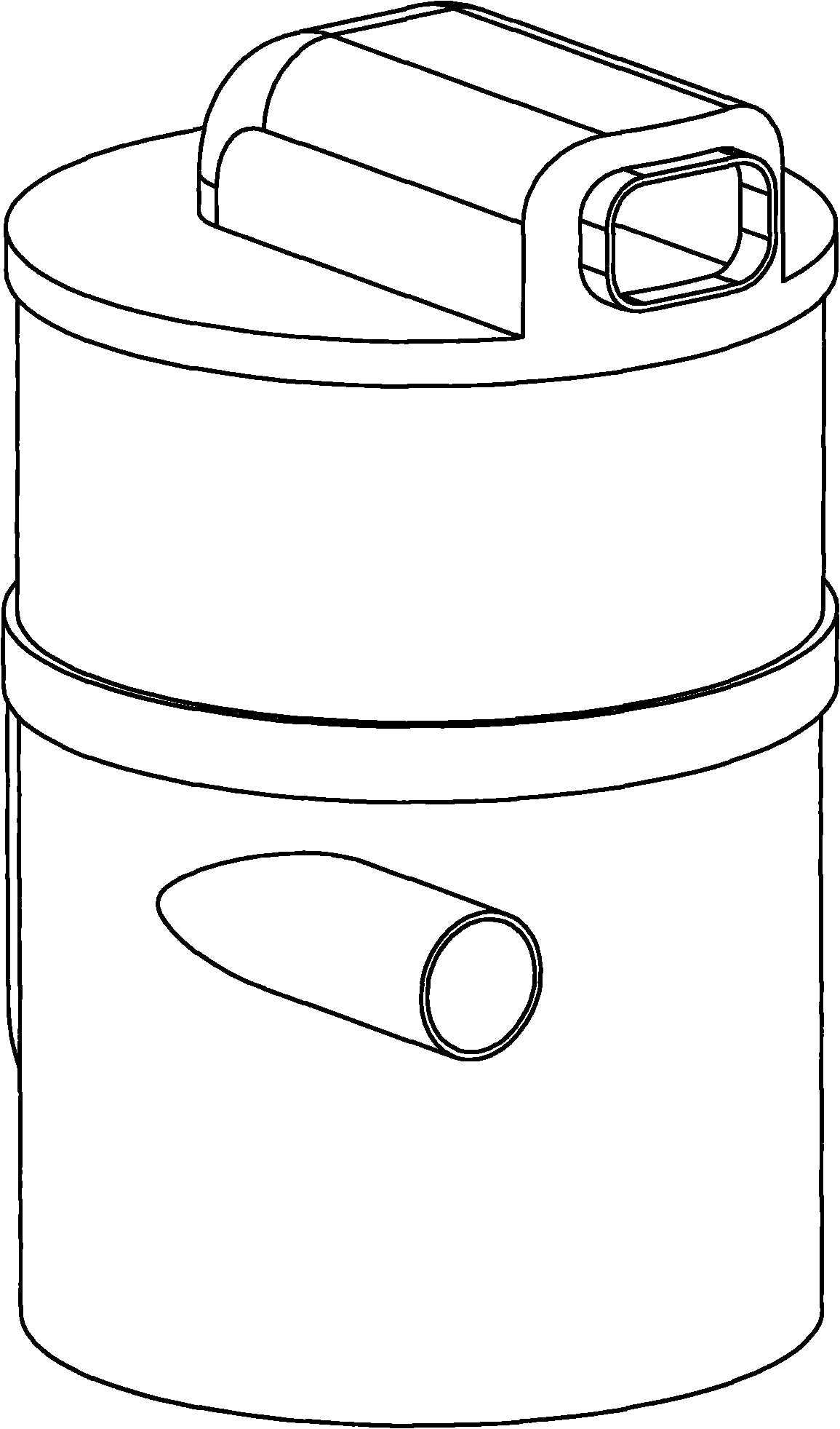
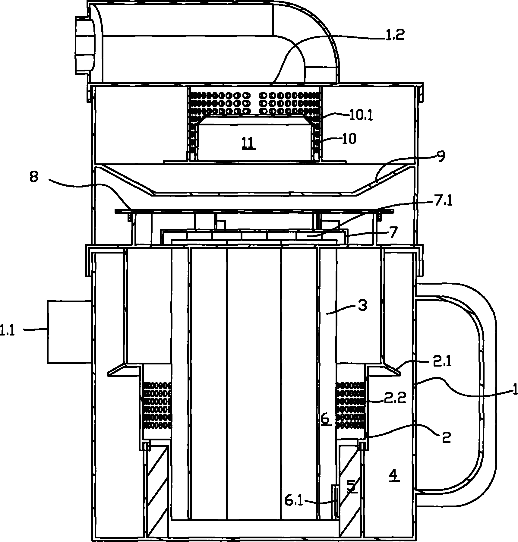
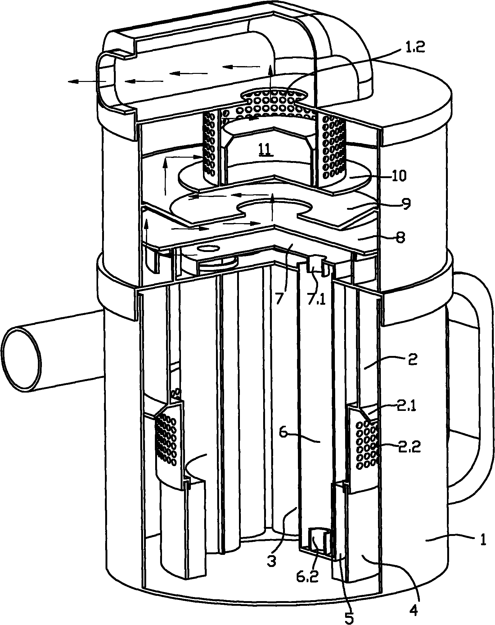
[0026] Such as Figure 1-6 As shown in the figure, a cyclone type water filter and dust collection device includes a dust bucket 1, a total air inlet 1.1, a total air outlet 1.2, a filter cartridge 2 as a primary filter, and a two-stage water filter 3, etc. Parts, the dust bucket 1 is arranged in the radial direction from the outside to the inside with the filter cartridge 2 and the water filter 3 that constitute the primary filter. The dust bucket 1, the filter cartridge 2 and the water filter 3 are arranged concentrically. Among them, the outer surface of the filter cartridge 1 is provided with an inclined dust cover 2.1 below the general air inlet, and a large particle dust dust chamber 4 is formed between the dust bucket 1, and the wall of the filter cartridge 2 is between the dust cover and the bottom edge. Filtration micropores 2.2 are ...


PUM


Abstract

The invention relates to a cyclonic water filtration dust collecting device, which comprises a dust barrel, a total air inlet and a total air outlet. The invention is characterized in that a filter vat forming a first-class filter, and a water filter are arranged on the dust barrel in the radial direction from outside to inside, wherein an inclined dust retaining hood is arranged at the lower part of the total air inlet outside the filter vat and forms a large-particle dust cavity with the dust barrel; filtering millipores communicating the inner side and the outer side are formed between the dust retaining hood and a bottom edge on the vat wall of the filter vat; an liquid collecting cavity is arranged between the filter vat and the water filter; a plurality of rotating water washing cylinders are arranged on the water filter; the side wall of the lower part of the rotating water washing cylinder is provided with a branch of an air inlet for guiding air stream to whirl upwards and the branch of the air inlet is dipped into the liquid in the liquid collecting cavity; and the outlets of the upper ends of the rotating water washing cylinders are centrally communicated with the total air outlet on the dust barrel. The invention has the advantages of compact and reasonable structure, small volume, more full contact of air-stream and water, good dust removing effect and more functions.

Description

technical field [0001] The invention relates to a dust collection device in a vacuum cleaner, in particular to a dust collection device with water filtration. Background technique [0002] With the continuous improvement of people's living standards and the development of science and technology, vacuum cleaners have entered thousands of households, and they have more and more functions. One of them is a vacuum cleaner with water filtration function. It can not only collect dust, but also use the water storage bucket in the vacuum cleaner to wash the dust in the airflow, so that the airflow is cleaner and less dusty. [0003] In the traditional dust collection device for water filtration, the front stage is generally a dust particle separator, and the rear stage is a water filter. The front stage dust particle separator and the rear stage water filter are generally designed side by side, resulting in a structure that is not compact enough. Reasonable, the volume is relativel...

Claims


Application Information

Patent Timeline
IPC IPC(8): A47L9/16A47L9/18
Inventor 胡海荣
Owner 胡海荣
Why Eureka
Try Eureka