Two-rotation one-movement-freedom-degree decoupling parallel mechanism

A degree of freedom, parallel technology, applied in the direction of manipulator, program control manipulator, metal processing mechanical parts, etc., to achieve the effect of easy calibration, reduced development cost, and small moment of inertia

Inactive Publication Date: 2011-09-14
SHANGHAI UNIV OF ENG SCI
View PDF1 Cites 0 Cited by
  • Summary
  • Abstract
  • Description
  • Claims
  • Application Information

AI Technical Summary

Problems solved by technology

Literature [Li Huiliang, Jin Qiong, Yang Tingli, a decoupling parallel mechanism with one translation and two rotations and its displacement analysis, Machinery Manufacturing and Research, Feb 2002, (1): 9-12, 14] proposed a triangular solution Two-rotation-one-movement parallel mechanism with coupling characteristics, but the output degree of freedom is not completely controlled by a single driver, and it is still a partially decoupled parallel mechanism. The literature and invention of the completely decoupled two-rotation-one-movement decoupled parallel mechanism have not yet been retrieved

Method used


Image

  • Two-rotation one-movement-freedom-degree decoupling parallel mechanism
  • Two-rotation one-movement-freedom-degree decoupling parallel mechanism
  • Two-rotation one-movement-freedom-degree decoupling parallel mechanism

Examples


Embodiment 1

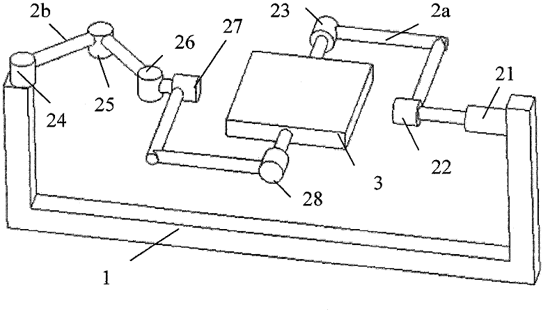
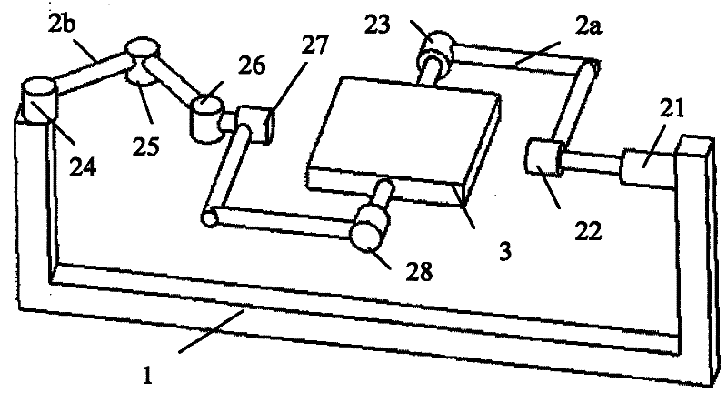
[0027] The present invention is a decoupling parallel mechanism with two rotations and one movement degree of freedom, such as figure 1 As shown, it consists of a frame 1, a moving platform 3 and two motion branch chains (the first movement branch chain 2a and the second movement branch chain 2b) connecting the frame 1 and the movement platform 3. The first movement branch chain The chain 2a includes a moving pair 21, a first rotating pair 22, a second rotating pair 23 and a rod. One end of the moving pair 21 is connected to the frame, and the other end is connected to the first rotating pair 22 and the second rotating pair 23 successively through a rod. Two rotating pairs 23 are connected to the moving platform 3, and the second kinematic branch chain 2b includes the third rotating pair 24, the fourth rotating pair 25, the fifth rotating pair 26, the sixth rotating pair 27, the seventh rotating pair 28 and the rod One end of the third rotating pair 24 is connected to the fram...

Embodiment 2

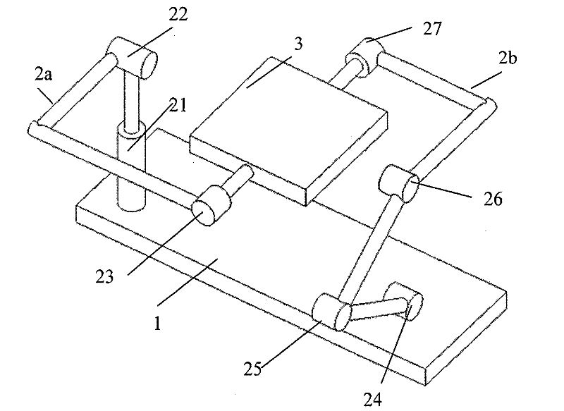
[0029] The present invention is a decoupling parallel mechanism with two rotations and one movement degree of freedom, such as figure 2 As shown, it consists of a frame 1, a moving platform 3 and two kinematic branch chains (the first kinematic branch chain 2a and the second kinematic branch chain 2b) connecting the frame 1 and the moving platform 3. The first kinematic branch chain 2a includes a moving pair 21, a first rotating pair 22, a second rotating pair 23 and a rod. One end of the moving pair 21 is connected to the frame, and the other end is sequentially connected to the first rotating pair 22 and the second rotating pair 23 through a rod. The rotating pair 23 is connected to the moving platform 3, and the second motion branch chain 2b includes the third rotating pair 24, the fourth rotating pair 25, the fifth rotating pair 26, the sixth rotating pair 27 and a rod, and one end of the third rotating pair 24 Connect the frame, and the other end is sequentially connecte...


PUM


Abstract

The invention relates to a two-rotation one-movement-freedom-degree decoupling parallel mechanism, which is composed of a rack (1), a moving platform (3) and two moving branch chains (2a), (2b) which connect the rack (1) and the moving platform (3), the axis of the sliding pair of the moving branch chain (2a) is vertical to the axis of a rotation pair which is parallel to three axes of the movingbranch chain (2b), and the moving branch chain (2a) and the moving branch chain (2b) comprise two coaxial rotation pairs. Compared with the prior art, the mechanism has less kinematic pair, the structure is simple, the rotary inertia is low, the movement response is fast, a single driving unit is only controlled by a single output freedom degree basically, the calibration is easy, the control is simple, the movement is controlled more accurately, and the development cost and the development cycle are greatly reduced.

Description

technical field [0001] The invention relates to a machine tool and an industrial robot, in particular to a virtual-axis numerical control machine tool with a parallel structure, and a new type of executive mechanism provided by the parallel robot. Background technique [0002] Parallel mechanisms are widely used in heavy-duty simulation equipment, robots, CNC machine tools, sensors and micro-operation fields. However, the drive units of the parallel mechanism are coupled, that is, the movement of the overall output platform of the parallel mechanism in any direction is the synthesis of the motions of all drive units, and the movement of each drive unit is combined with the overall movement of the parallel mechanism (i.e. input and output ) is non-linear. This characteristic leads to complex control of parallel mechanism, difficult calibration, and restricts the improvement of accuracy. Therefore, how to achieve decoupling of parallel mechanisms to simplify control and cali...

Claims


Application Information

Patent Timeline
Patent Type & Authority Patents(China)
IPC IPC(8): B25J9/08B23Q1/48
Inventor 张帆徐正好胡义刚成琼沈耀仁刘燕
Owner SHANGHAI UNIV OF ENG SCI
Why Eureka
Try Eureka