Drive axle shaft clutch

A clutch and drive axle technology, applied in clutches, control devices, mechanical equipment, etc., can solve the problems of inability to cut off torque, dragging and energy consumption of ineffective linkages, so as to reduce mechanical energy loss and extend light-load gliding distance. , Significant fuel-saving effect

Inactive Publication Date: 2010-07-21
于宥源
View PDF5 Cites 12 Cited by
  • Summary
  • Abstract
  • Description
  • Claims
  • Application Information

AI Technical Summary

Problems solved by technology

[0003] At present, the drive axles installed on various motor vehicles cannot cut off the torque. When the vehicle needs to be lightly loaded durin

Method used


Image

  • Drive axle shaft clutch
  • Drive axle shaft clutch
  • Drive axle shaft clutch

Examples


Example Embodiment

[0017] The present invention will be described in detail below in conjunction with the accompanying drawings and specific embodiments.

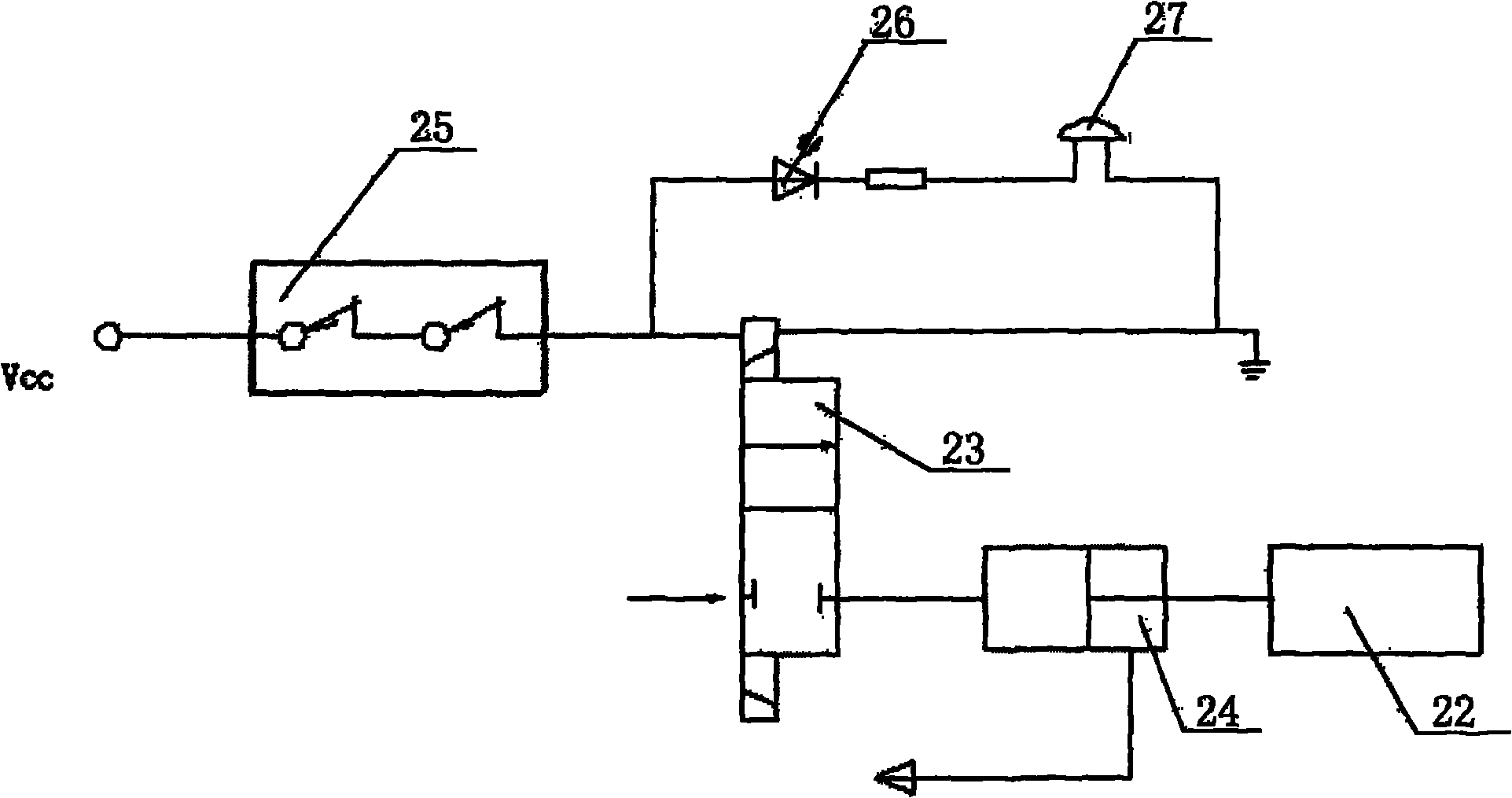
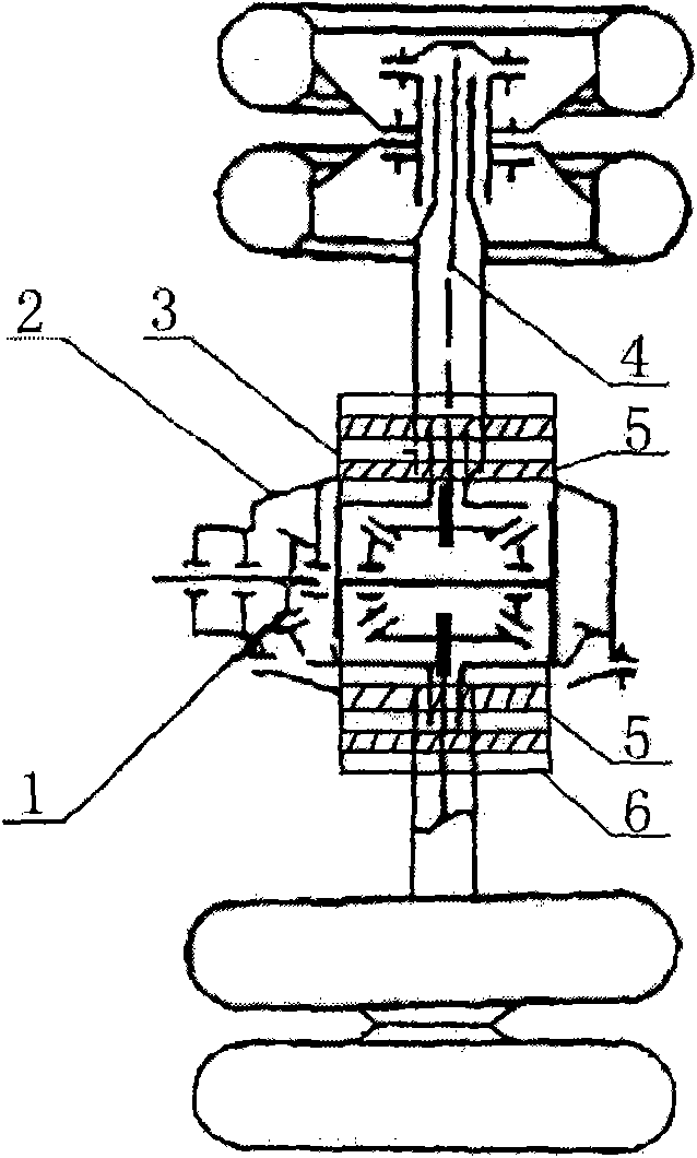
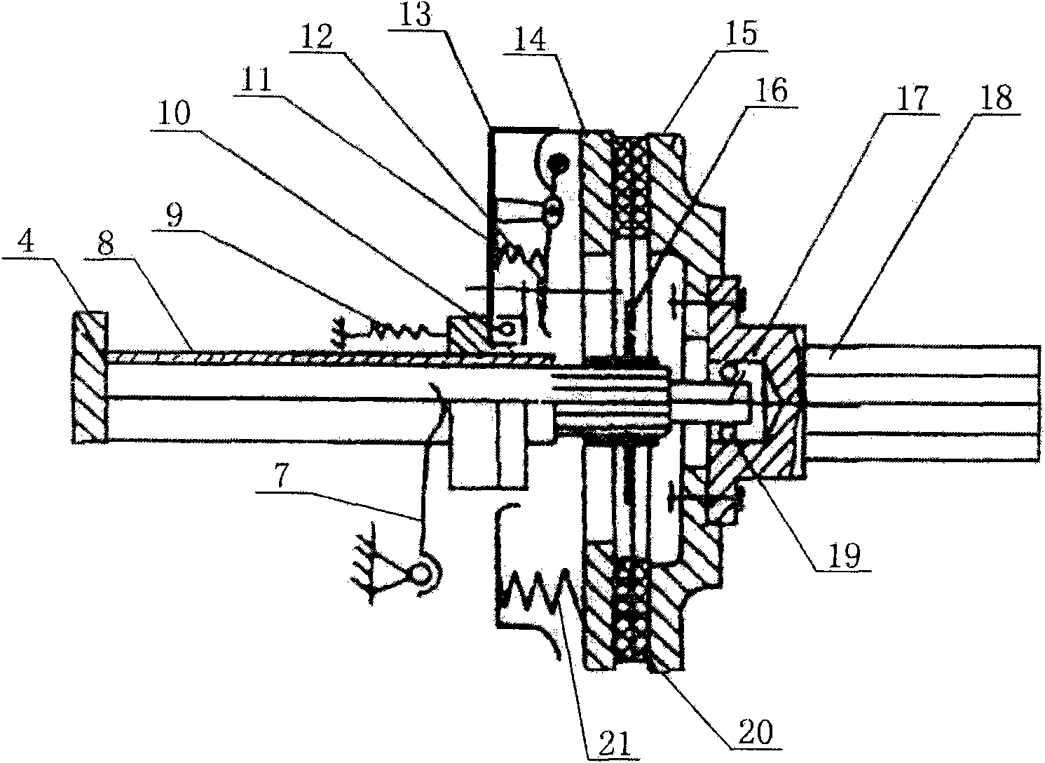
[0018] see figure 1 , including the axle shaft of the drive axle, on which the half axle clutch is arranged, the installation inspection hole for the clutch and the differential is arranged on the axle casing of the axle axle, the release lever 22 of the axle clutch is connected with the air valve 23 and the air storage tank 24 respectively Connection, between the air valve 23 and the brake mechanism, an alarm circuit composed of light-emitting diodes 26 and buzzer 27 is connected. When the car is running, when the driver's foot leaves the accelerator pedal, the electronically controlled air valve is energized. Make the high-pressure gas push the half-shaft clutch release lever 22, make the half-shaft clutch separate, and the engine and the drive axle are disengaged, thereby reducing the consumption of mechanical energy when the drive axle is...


PUM


Abstract

The invention relates to a vehicle clutch, in particular to a drive axle shaft clutch. At present, the drive axle installed on various motor vehicles is not capable of cutting off the torque; when the vehicle needs light loading in driving, since all pulling and non-effect interlocking pieces cannot be cut off, a large amount of energy is consumed, and the internal friction is always neglected since the advent of vehicles. The drive axle shaft clutch comprises a drive axle shaft; an axle shaft clutch is installed on the drive axle shaft; the housing of the drive axle is provided with a clutch and the mounting inspecting hole of a differential gear; the disengaging bar of the axle shaft clutch is respectively connected with an air valve and an air cylinder; and an alarming circuit comprising a light-emitting diode and a buzzer is installed between the air valve and a brake mechanism. The clutch is capable of safely, reliably and efficiently cutting off or bonding power in time, and has small volume, high transmission efficiency and low cost.

Description

1. Technical field [0001] The invention relates to an automobile clutch, in particular to a drive axle half shaft clutch. 2. Background technology [0002] The drive axle is the last assembly on the transmission system of the car chassis, consisting of the final reducer, differential, half shaft and axle housing. The main reducer increases the torque transmitted through the transmission and the universal joint drive shaft, and reduces the speed to meet the needs of the car. The differential can make the speed of the driving wheels on the left and right sides asynchronous, meeting the needs of vehicle steering, driving on uneven roads, and vehicle turning. The half shaft transmits the power output from the differential to the drive wheels on both sides. In addition to being used to install and support the reducer, differential, and axle shaft to form the assembly shell, the axle housing also supports the driving wheels and bears various forces and moments on the driving whe...

Claims


Application Information

Patent Timeline
IPC IPC(8): B60K17/02
CPCF16D2500/10425F16D2500/7101B60K17/02F16D48/02
Inventor 于宥源冯忠绪周乾坤沈建军
Owner 于宥源
Why Eureka
Try Eureka