Three-phase biological fluidized bed
A technology of biological fluidized bed and three-phase separator, which is applied in the field of wastewater treatment, can solve the problems of poor practical applicability and poor treatment effect, and achieve the effect of shortening the film-hanging time
- Summary
- Abstract
- Description
- Claims
- Application Information
AI Technical Summary
Problems solved by technology
Method used
Image

Examples
Embodiment Construction
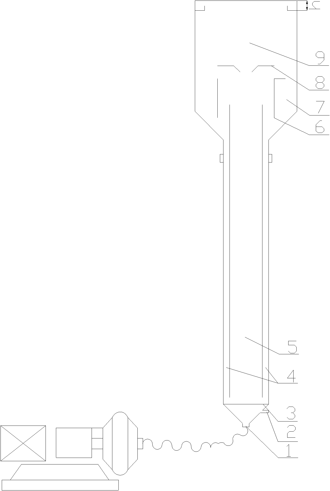
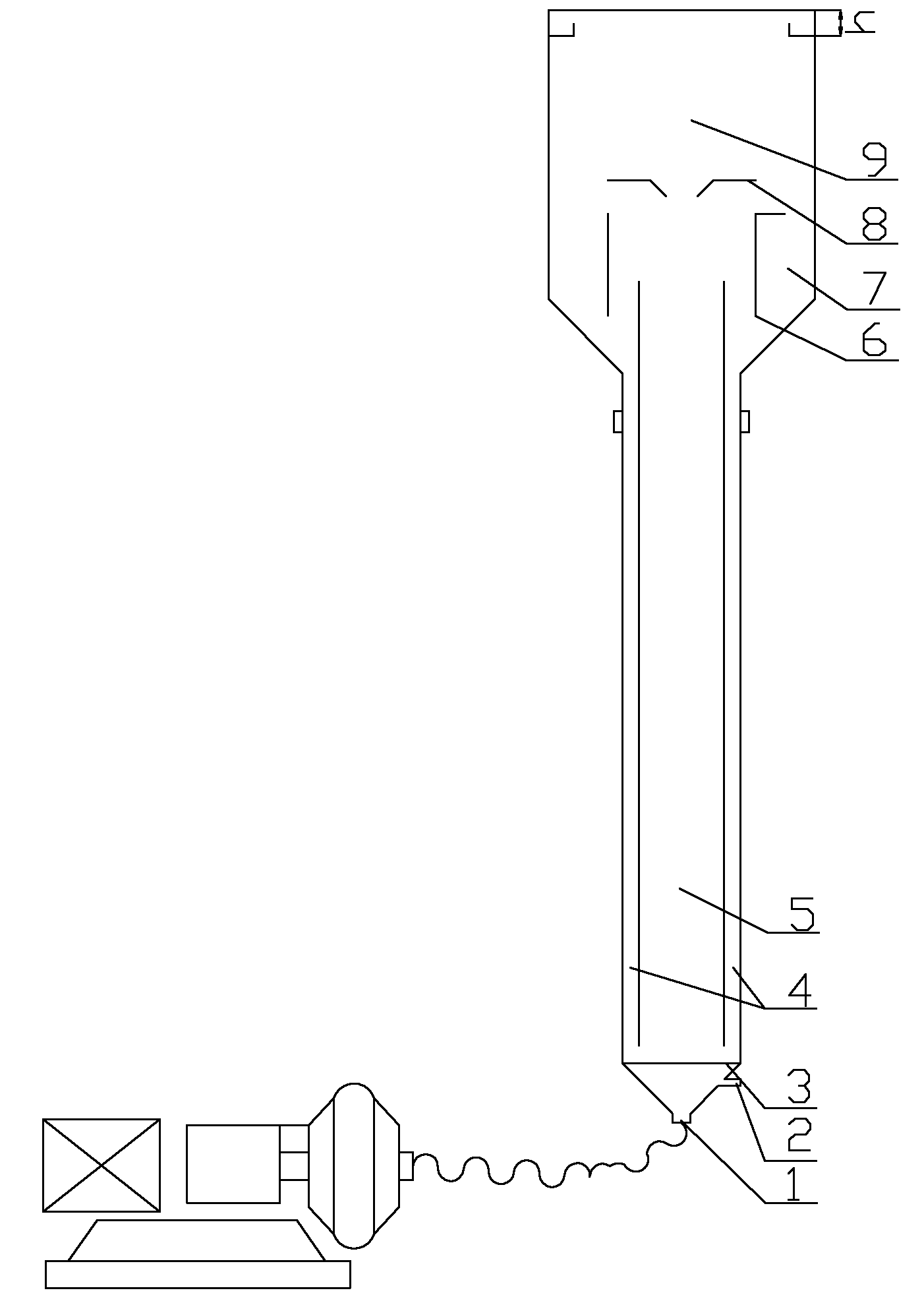
[0017] The present invention is described in further detail below in conjunction with accompanying drawing:
[0018] see figure 1 , a three-phase biological fluidized bed, comprising a guide tube, a three-phase separator 8, a baffle 6, a partition, a water inlet 2, an air inlet 1 and a plate air distributor 3; the three-phase separator 8 And the baffle plate 6 is arranged on the top of the guide tube, the three-phase separator 8 and the top of the guide tube form a gas-liquid separation zone 9, and the solid-liquid separation zone 7 is formed between the baffle plate 6 and the inner wall of the guide tube; In the middle of the guide tube, a downflow area 4 is formed between the partition and the inner wall of the guide tube, and an upflow area 5 is formed between the partitions; the plate air distributor 3, the water inlet 2 and the air inlet 1 are from top to bottom. Set up at the bottom of the guide tube in turn. The guide tube is funnel-shaped.
[0019] 1. Design and man...
PUM
 Abstract
Description
Claims
Application Information
 - R&D
- Intellectual Property
- Life Sciences
- Materials
- Tech Scout
- Unparalleled Data Quality
- Higher Quality Content
- 60% Fewer Hallucinations
Browse by: Latest US Patents, China's latest patents, Technical Efficacy Thesaurus, Application Domain, Technology Topic, Popular Technical Reports.
© 2025 PatSnap. All rights reserved.Legal|Privacy policy|Modern Slavery Act Transparency Statement|Sitemap|About US| Contact US: help@patsnap.com