Energy storage stapling machine sending out stitching needle groove from front

An energy storage type, stapler technology, applied in the field of staplers, can solve the problems of small labor-saving ratio of the lever arm, not fast, inconvenient to take and take, etc., and achieves the effect of reasonable ratio of the lever arm and good effect.

Inactive Publication Date: 2010-07-28
廖金志
View PDF9 Cites 4 Cited by
  • Summary
  • Abstract
  • Description
  • Claims
  • Application Information

AI Technical Summary

Problems solved by technology

But a class of energy storage type stapler known at present is as Chinese patent No.: the stapler of ZL94215495.9, all there is a common defective: under its idle state, because the staple sheet is all at the lower end of box front, So stop book needles from being loaded from the front of the box
The disadvantage of loading the needles from the tail or bottom of the stapler is that it is inconvenient and inconvenient to install and change the needles, and it is easy to fall the needles when loading loose needles or a small number of needles, which is difficult to install; It is inconvenient to take and hold when changing book needles, and the quality of book needles is not high
[0006] 3) The original Chinese patent number is: the stapler made by 2006100634464. When the stapler is in the idle state, when it is located at the upper part of the front end of the box, the labor-saving lever and spring of the energy storage device are farther away from the lower part of the box. The stapler It can only be made bigger, the proportion of the force arm of the labor-saving lever is difficult to be reasonable, the proportion of force-saving force arm is made smaller, and the stapler cannot be made more labor-saving

Method used


Image

  • Energy storage stapling machine sending out stitching needle groove from front
  • Energy storage stapling machine sending out stitching needle groove from front
  • Energy storage stapling machine sending out stitching needle groove from front

Examples


Embodiment 1

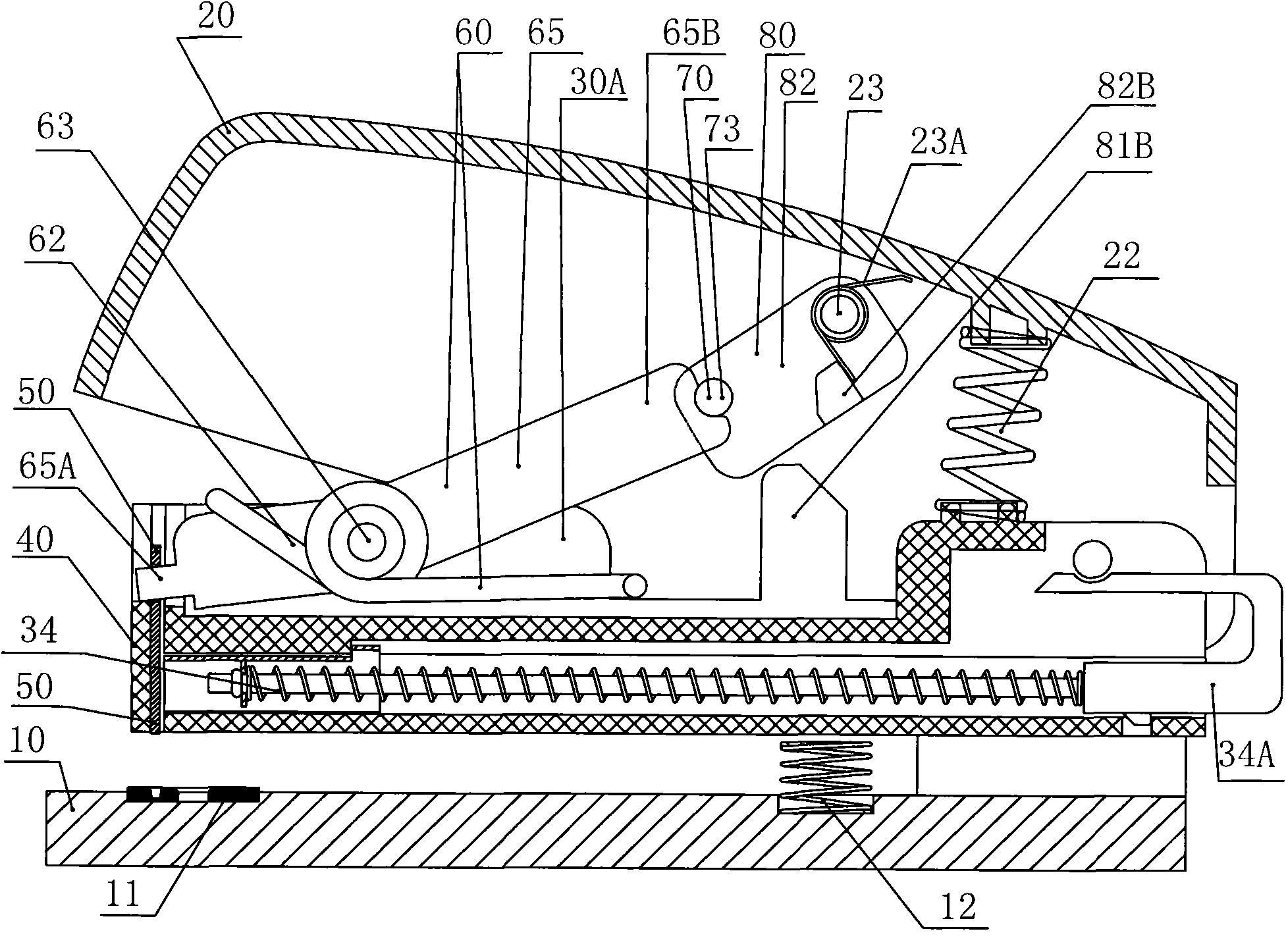
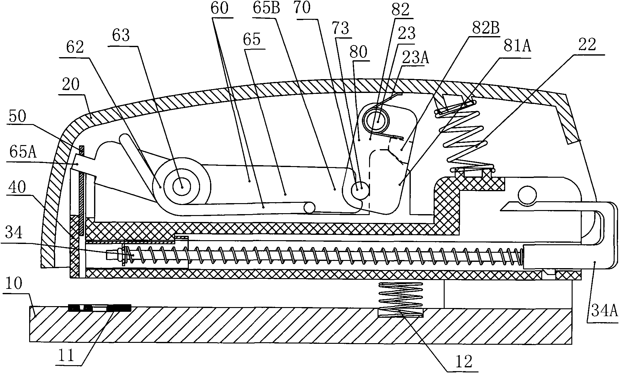
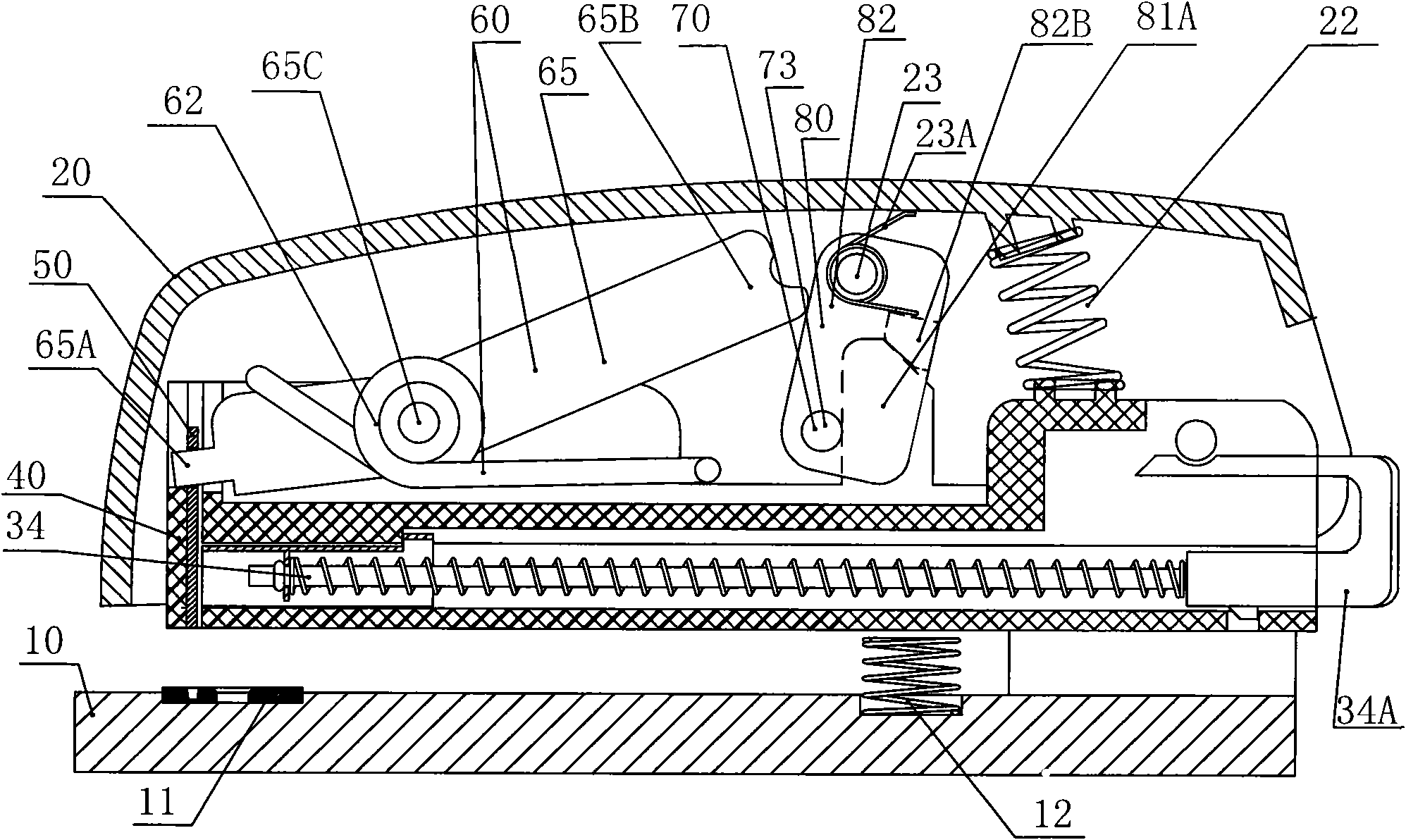
[0040] Such as Figure 4-13 , which are schematic diagrams showing the assembly and disassembly structures of Embodiment 1 of the present invention in various states; Figure 6~7 It is a three-dimensional schematic diagram of the dismantling structure of the staple sheet, the needle groove and the chute frame related to Embodiment 1 of the present invention.

[0041] Embodiment 1 of the present invention includes a base 10, an upper cover 20, a box 40 with a book needle groove 30 fitted therein, and a staple sheet 50 for pressing the book needles in the book needle groove 30, and the sliding fit in the box 40 is elastic. Needle pusher 34 and needle presser plate 40B. On the base 10, a needle plate 11 is provided at the position corresponding to the falling of the nail sheet 50, and a bottom spring 12 is also provided on the base 10; the box 40 is hinged on the base, and the upper cover 20 is in the box. 40, and hinged on the base; the staple piece 50 slides up and down to fi...

Embodiment 2

[0049] Such as Figure 14 , which is a schematic cross-sectional view of the structure of the book needle slot popping up and loading the needle with the leaf spring instead of the torsion spring energy storage in Embodiment 2 of the present invention; except that the parts such as the staple sheet and the box need to increase or decrease the corresponding structure to match the leaf spring, other structures All are similar to Example 1.


PUM


Abstract

The invention relates to an energy storage stapling machine sending out a stitching needle groove from the front. The energy storage stapling machine comprises a pedestal, an upper cover, the stitching needle groove, a box and a needle stitching piece, wherein an elastic needle pushing apparatus is in slide fit in the stitching needle groove; the box is hinged on the pedestal; the upper cover is hinged on the box or coaxially or non-coaxially hinged on the pedestal together with the box; the front end of the box is provided with a notch which allows the stitching needle groove to enter and exit; the vertical plane of the needle stitching piece is provided with a bump or a sliding groove; the middle or middle upper part of the main vertical plane of the needle stitching piece is provided with a butt joint hole; the front end part of the stitching needle groove is provided with a chute which accommodates the bump and limits upward and downward slide of the bump or provided with a lug boss which is in butt joint with the sliding groove; an elastic energy storage device and an energy releasing switch are arranged between the box and the upper cover; and a trigger end of the elastic energy storage device is movably butted in the butt joint hole of the needle stitching piece. The needle stitching piece of the stapling machine is ejected along with the stitching needle groove, so thestitching needles can be conveniently and rapidly replaced and good stitching needle mounting effect is achieved; and compared with an ordinary stapling machine, the energy storage stapling machine saves about 70 percent of force.

Description

technical field [0001] The present invention relates to an office stationery, more specifically, the present invention relates to a stapler. Background technique [0002] The energy-storage stapler uses elastic parts (such as springs, leaf springs, torsion springs, etc.) to store energy, and then releases the stored energy instantly, driving the staple sheet to impact the staples instantly, realizing the function of high-energy staples, which is labor-saving , good nail effect and so on. But a class of energy storage type stapler known at present is as Chinese patent No.: the stapler of ZL94215495.9, all there is a common defective: under its idle state, because the staple sheet is all at the lower end of box front, So stop the needles from being loaded into the front end of the case. For a long time, the structural problem that this type of stapler pops out from the front end of the box to load the needles has not been solved, and only a poor method of loading the needles...

Claims


Application Information

Patent Timeline
Patent Type & Authority Applications(China)
IPC IPC(8): B42B4/00B25C5/02
Inventor 廖金志
Owner 廖金志
Why Eureka
Try Eureka