Longitudinal axial flow threshing device of whole-feed combine harvester

A technology for combine harvesters and threshing devices, which is applied in threshing equipment, agricultural machinery and implements, and applications. It can solve the problems of clogging of the feed inlet of the threshing drum, high cleaning loss, and small cleaning screen area, and achieve enhanced speed and efficiency. The effect of spreading strength, reducing the intensity of material handling, and correcting the unevenness of conveying materials

Inactive Publication Date: 2010-08-04
XINGGUANG AGRI MACHINERY
View PDF5 Cites 12 Cited by
  • Summary
  • Abstract
  • Description
  • Claims
  • Application Information

AI Technical Summary

Problems solved by technology

One of the disadvantages is that the grain cleaning loss is larger than that of the traditional horizontal axial flow threshing device. The reason is that the threshing chamber of the horizontal vertical threshing drum structure is narrower than the horizontal horizontal threshing drum structure, and the length of the threshing chamber Because the installation position is basically the same, the cleaning screen area of ​​the vertical axial flow threshing device is smaller than that of the horizontal axial flow threshing device. When the amount of cleaning materials is constant, the cleaning loss will be corresponding It is higher than the horizontal axial flow threshing device; the second disadvantage is that the crop feeding direction is 90 degrees to the rotation direction of the threshing drum, which is not as smooth as the horizontal horizontal structure, and the middle conveying trough is hung in front of the threshing chamber The linear speed of the conveying drum inside is not enough, that is, the throwing force is not enough, which is not enough to make the threshing drum fully grab the straw. In order to make up for this defect, the feeding section of the existing vertical threshing drum is designed as a cone with auger blades However, the effect is still not ideal, that is, when harvesting tall crops, especially crops with lodging and diseased stems, the feed inlet of the threshing drum will still be blocked

Method used


Image

  • Longitudinal axial flow threshing device of whole-feed combine harvester
  • Longitudinal axial flow threshing device of whole-feed combine harvester
  • Longitudinal axial flow threshing device of whole-feed combine harvester

Examples


Embodiment Construction

[0015] The present invention will be further described below with reference to the accompanying drawings.

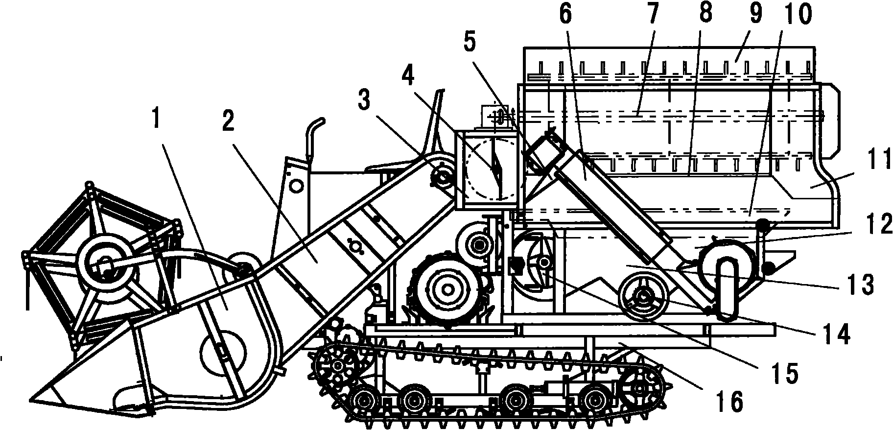
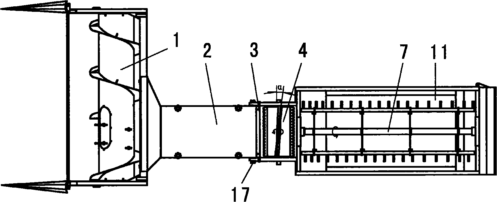
[0016] A threshing chamber 11 is installed on the chassis 16 of the full-feed combine harvester, and an intermediate delivery trough 2 is connected between the front end of the threshing drum of the threshing chamber 11 and the header 1 of the harvester. Inside the threshing chamber 11, a vertical threshing drum 7 whose axis is parallel to the advance direction of the harvester, a concave plate sieve 8, and a cleaning sieve 10 are installed from top to bottom. Inner front, fan 15 is installed at the bottom of cleaning sieve 10, and the threshing chamber space at the bottom of cleaning sieve 10 is formed by V-shaped plate respectively before main feed bin 13 and rear secondary feed bin 12. The full concentrate in the front main silo 13 is conveyed to the grain bin of the harvester through the conveying auger 14; Composed of a small re-extraction drum and a secondary lift...


PUM


Abstract

The invention discloses a longitudinal axial flow threshing device of a whole-feed combine harvester. A charging chamber connected with a threshing chamber into a whole is added between the upper end of a middle conveying trough and the front end of a longitudinal threshing cylinder; the feeding chamber is internally provided with a transverse charging cylinder; the upper end of the middle conveying trough is connected with the inlet of the charging chamber; the bottom surface of the outlet of the charging chamber is connected with a concave sieve plate by a transition plate; the output end of a secondary re-threshing transporter is connected to the front part of the left side of the threshing chamber and is connected above the transition plate. Because of adding the charging cylinder, the improved threshing device of the invention greatly strengthens feed speed and throwing strength to the threshing cylinder charging so as to effectively avoid the detect that the longitudinal axial flow threshing chamber of the whole-feed combine harvester has large possibility of blocking; meanwhile, the output end of the secondary re-threshing transporter is connected above the charging transition plate of the threshing cylinder connected with the front end of the concave sieve plate instead of being above the traditional sorting screen, thus greatly lightening the material processing strength of the sorting screen, and reducing material sorting loss.

Description

technical field [0001] The invention relates to a threshing device of a full-feed combine harvester. Background technique [0002] The threshing device of the existing full-feed combine harvester generally has a threshing chamber in its structure. The threshing drum, concave plate sieve, and cleaning sieve are installed in the threshing chamber from top to bottom. The threshing chamber space at the bottom of the cleaning sieve is the cleaning chamber. , the front end of the cleaning room is equipped with a fan, and the space of the cleaning room is composed of V-shaped plates respectively. A secondary horizontal conveying auger is installed under the silo, and the outlet end of the secondary horizontal conveying auger is connected with a secondary re-removal drum, and the radial side of the secondary re-removal drum is connected with a secondary lifting conveying auger. The secondary horizontal conveying auger, the secondary re-extracting drum and the secondary lifting conv...

Claims


Application Information

Patent Timeline
Patent Type & Authority Applications(China)
IPC IPC(8): A01F7/02A01F12/12A01F12/18A01F12/20
Inventor 张奋飞邵尔青李国良章沈浩
Owner XINGGUANG AGRI MACHINERY
Why Eureka
Try Eureka