Novel laser welding piston with forged steel structure

A technology of laser welding and forging steel, applied in pistons, engine components, machines/engines, etc., it can solve the problems of controlling or reducing oil consumption without a clear structural plan, achieving small deformation, increasing flexibility, and increasing structural rigidity. Effect

Inactive Publication Date: 2010-08-04
SHANDONG BINZHOU BOHAI PISTON
View PDF8 Cites 15 Cited by
  • Summary
  • Abstract
  • Description
  • Claims
  • Application Information

AI Technical Summary

Problems solved by technology

The patent does not propose a clear structural solution for the control or reduction of oil consumption

Method used


Image

  • Novel laser welding piston with forged steel structure
  • Novel laser welding piston with forged steel structure
  • Novel laser welding piston with forged steel structure

Examples


Embodiment 1

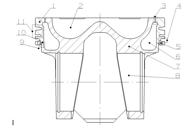
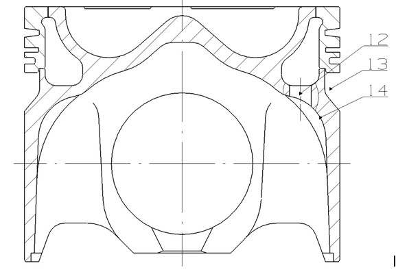
[0025] as attached figure 1 , figure 2 As shown, the new laser welded forged steel structure piston includes forged piston ring body 1 and piston body 7. The piston ring body 1 and piston body 7 are first combined through the welding area 3 and the mating area 10, and the The welding area 3 is welded and formed; the upper part of the piston body 7 is processed to form the combustion chamber 2, and the outer circle of the piston ring body 1 is processed to form a ring groove (including the lower oil ring groove 4 and several gas ring grooves 11 in the upper part). A closed cooling oil cavity 6 is formed between the combustion chamber 2, and the cooling oil cavity 6 communicates with the outside or the inner cavity 14 through the oil inlet and outlet holes 12, and the position where the side of the piston body 7 contacts the piston ring body 1 is processed with an annular groove 9 , There is a ring belt between the oil ring groove 4 and the ring groove 9, and a number of Ge oi...

Embodiment 2

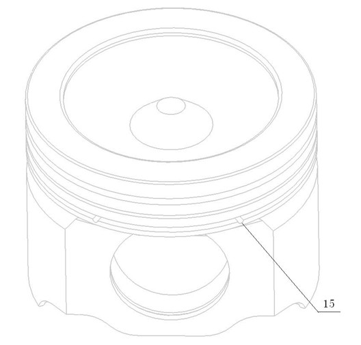
[0033] In this embodiment, several oil return blind holes 15 can also be designed, and the oil return blind holes 15 are arranged on the lower side of the oil ring groove 4. The centerline of the oil return blind holes 15 is on the lower side of the oil ring groove 4 or higher than the oil On the lower side of the ring groove 14, the axial direction of the oil return blind hole 15 is perpendicular to the centerline of the piston. Oil at the oil ring groove 4, especially at the bottom, flows back into the annular groove 9 through the oil return blind hole 15 on the lower side of the oil ring groove 4 and the ring belt with a smaller diameter. The rest are the same as in Embodiment 1 and will not be repeated here.

Embodiment 3

[0035] The difference from Embodiment 1 is that: under the piston ring groove, the annular groove 9 processed above the piston body 7 communicates with the piston inner cavity 14 in the direction perpendicular to the pin hole 8 .

[0036] The rest are the same as in Embodiment 1, and will not be repeated here.

[0037]

[0038]

[0039]

[0040]

[0041]

[0042]


PUM


Abstract

The invention relates to a novel laser welding piston with a forged steel structure. The piston comprises a forged piston ring body and a piston body, wherein the piston ring body and the piston body are welded by laser; a closed cooling oil chamber is formed between the piston ring body and the piston body and is communicated with the external through an oil inlet hole and an oil outlet hole; the lower part of the piston ring body is provided with an oil ring groove; the piston body corresponding to the position of the oil ring groove is provided with an annular groove; a girdle band is arranged between the oil ring groove and the annular groove; the girdle band is provided with a plurality of oil return holes communicating the oil ring groove and the annular groove; or the lower side of the oil ring groove is provided with a plurality of level oil return blind holes. The piston reduces weight of the piston, and increases flexibility of the piston body; and the oil return holes or the level oil return blind holes are favorable for back flow of machine oil of the oil ring groove, particularly the machine oil at the bottom of the oil ring groove so as to prevent the spilling of the machine oil caused by high pressure of the machine oil, and contribute to reducing machine oil consumption and harmful emissions of motors.

Description

[0001] technical field [0002] The invention relates to a piston, in particular to a novel laser-welded forged steel structure piston. Background technique [0003] In the past ten years, engine design and manufacturing technology have been rapidly improved, especially diesel engines are developing towards high power and high load, and the degree of strengthening has been continuously improved. The explosion pressure has exceeded 20MPa. At the same time, the emission requirements have become stricter. Although the quality piston has the advantages of light weight, the aluminum material has gradually been unable to meet the requirements of high power, high reinforcement and low emission of the engine. To this end, domestic and foreign piston design and manufacturers are committed to the design and development of new pistons with high reliability and meeting economical and emission requirements, such as aluminum pistons with liquid die forging ceramic fiber structures, pendul...

Claims


Application Information

Patent Timeline
Patent Type & Authority Applications(China)
IPC IPC(8): F02F3/22
Inventor 林风华张庆远马学军石小明郭书刚马呈新王世利郭伟
Owner SHANDONG BINZHOU BOHAI PISTON
Why Eureka
Try Eureka