Device and method for automatically detecting light extinction rate of smoke

A technology of dimming rate and smoke, which is applied in the direction of measuring devices, material analysis through optical means, instruments, etc., can solve the problems of system performance degradation, lack of response performance, accurate and effective judgment, etc., to achieve convenient installation and use, and improve technology Level, long service life effect

Inactive Publication Date: 2010-08-04
SHENYANG FIRE RES INST OF THE MIN OF PUBLIC SECURITY
View PDF0 Cites 6 Cited by
  • Summary
  • Abstract
  • Description
  • Claims
  • Application Information

AI Technical Summary

Problems solved by technology

[0003] 1. The feature of adjustable sensitivity can easily lead to alarm lag;
[0004] 2. The aging of the smoke detector leads to a decline in the performance of the system;
[0005] 3. Insufficient on-site testing equipment cannot guarantee the good operation of the system
[0006] At present, in the acceptance process of fire protection engineering, since there is no corresponding testing equipment, most of them are tested by lighting cigarettes or cigarette lighters. However, the smoke sources of these equipment are neither standard, stable nor repetitive. At the same time, these smoke test equipment also lack the means to detect the smoke concentration, so it is impossible to make a quantitative judgment on whether it meets the corresponding fire detection response perform...

Method used


Image

  • Device and method for automatically detecting light extinction rate of smoke
  • Device and method for automatically detecting light extinction rate of smoke
  • Device and method for automatically detecting light extinction rate of smoke

Examples


Embodiment Construction

[0018] The detailed structure of the smoke dimming rate automatic detection device and control method of the present invention is illustrated by the embodiments and accompanying drawings.

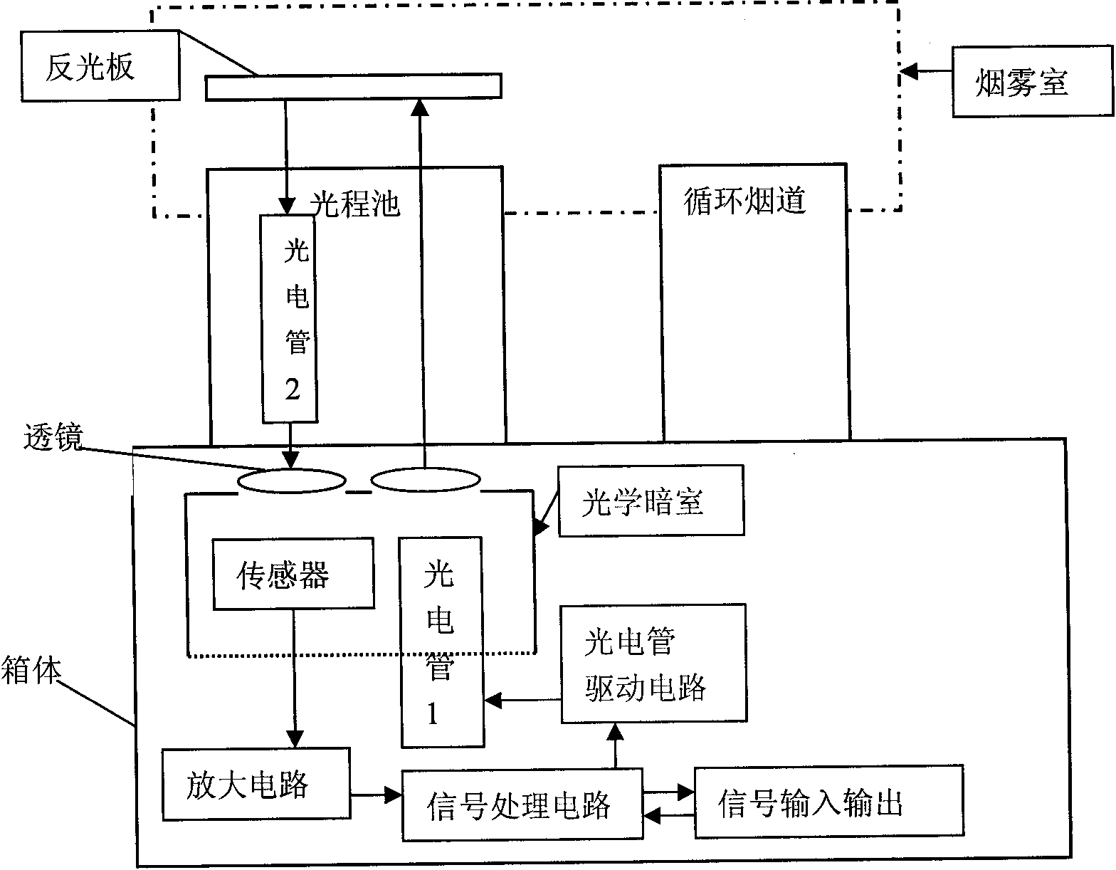
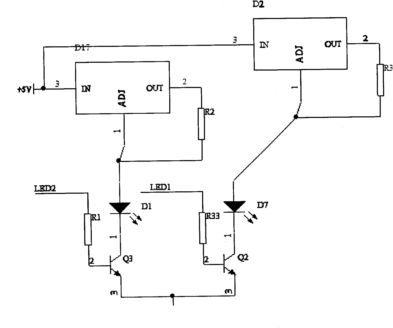
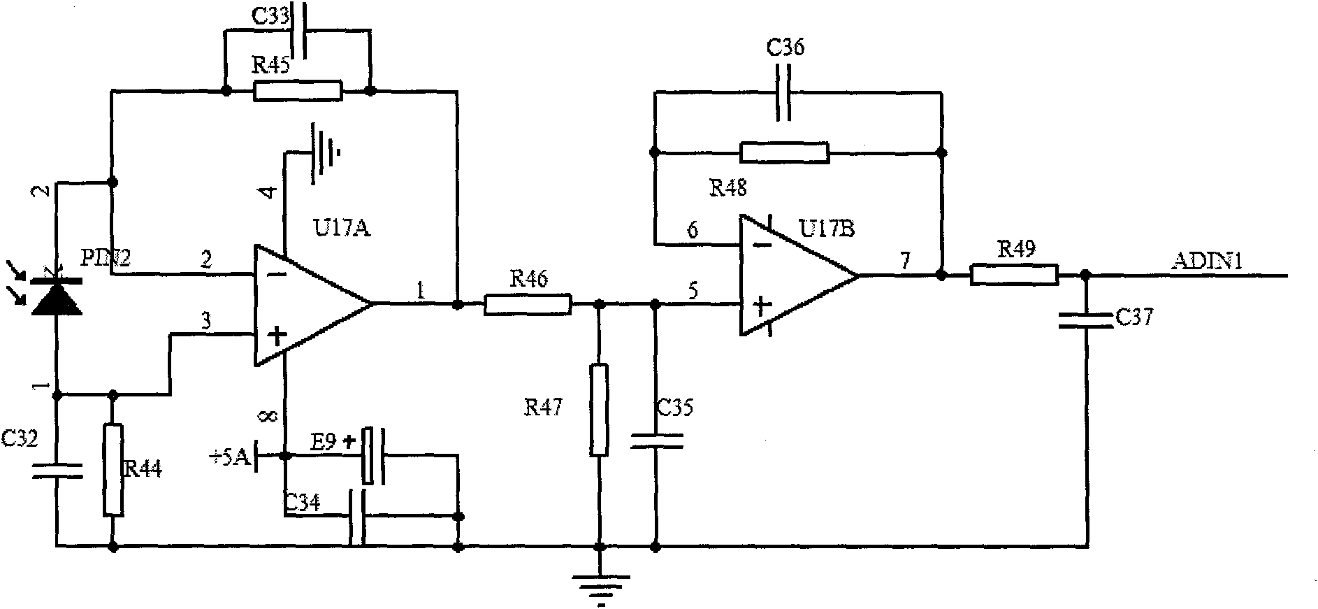
[0019] Its overall structure is as figure 1 As shown, phototube 1 and phototube 2 are respectively connected to the phototube driving circuit, and the phototubes are respectively driven by triodes, such as figure 2 As shown; the output of the sensor passes through the amplifying circuit, the signal processing circuit is connected with the input and output circuit, and the signal amplifying circuit is composed of a two-wire amplifier, such as image 3 As shown, the sensor used is model S1133-01;

[0020] The signal processing circuit is completed by a single block U11, the signal input and output circuit is controlled by a triode, the power-on high level is reception, and the power-on low level is transmission, and the input and output of the signal are controlled by the triode. The signal...


PUM


Abstract

The invention relates to a device and a method for automatically detecting the light extinction rate of smoke, which belongs to the technical field of fire monitoring, and comprises a smoke signal part and a control circuit part, wherein the smoke signal part comprises a smoke chamber, and reflective plates are arranged in the smoke chamber; a control circuit is arranged in a box body, and an optical path pool and a circulating flue are arranged between the two parts; an optical darkroom is arranged below the box body, and a phototube 1 and a sensor are arranged in the darkroom; a lens is respectively and correspondingly arranged above the phototube 1 and the sensor, and the optical path pool is arranged above the two lenses; a phototube 2 is arranged in the optical path pool corresponding to the sensor, and the reflective plates which are parallel to the optical path pool are arranged above the optical patch pool; and the sensor in the optical darkroom is in output connection with an amplifier circuit and is connected with a signal input and output circuit by a signal processing circuit, and the phototube 1 in the optical darkroom is connected with a phototube driving circuit. The device for detecting the light extinction rate of smoke has simple structure, convenient installation and use, long service life, and is suitable for detection in various fire facilities.

Description

technical field [0001] The invention belongs to the technical field of fire monitoring, in particular to a detection device and a detection method using smoke signals as detection information. Background technique [0002] At present, with the rapid and steady development of the economy, more and more attention has been paid to the fire protection profession, and more and higher requirements have been put forward for the fire protection industry. Smoke detectors are the mainstream products in automatic fire detection products. Of the approximately 5 million detectors installed, approximately 70% are of this type. In future applications, smoke detectors will still maintain their dominant position. Its application has the following disadvantages: [0003] 1. The feature of adjustable sensitivity can easily lead to alarm lag; [0004] 2. The aging of the smoke detector leads to a decline in the performance of the system; [0005] 3. Insufficient on-site testing equipment ca...

Claims


Application Information

Patent Timeline
IPC IPC(8): G01N21/17
Inventor 王勇俞董文辉梅志斌宋珍
Owner SHENYANG FIRE RES INST OF THE MIN OF PUBLIC SECURITY
Why Eureka
Try Eureka