Photoelectronic device for touch response of musical instrument

A photoelectric device and keyboard technology, which is applied to stringed instruments, electroacoustic instruments, instruments, etc., can solve the problems of magnification error, error-prone, poor anti-interference, etc., and achieve the effects of simplified assembly, reduced cost and high precision

Inactive Publication Date: 2010-08-04
SHANGHAI JIUGE MUSIC INSTR
View PDF0 Cites 12 Cited by
  • Summary
  • Abstract
  • Description
  • Claims
  • Application Information

AI Technical Summary

Problems solved by technology

[0006] Non-contact foreign countries also use a set of infrared light emitting and receiving semiconductor components to detect the intensity of the light signal. As the photosensitive receiving tube works in the linear region of the characteristic curve, the manufacturing error and assembly error such as the magnification error of the photosensitive receiving tube will easily produce wrong results, and the consistency is not as good as that of the photosensitive receiving tube in the two sets of photoelectric switches. The photosensitive receiving tube only works in the saturation area or cut-off reliable
Since the output of the photosensitive receiving tube is an analog signal, an additional auxiliary circuit needs to be added to convert it into a digital signal. This detection method has complex circuits, high cost, and poor anti-interference performance.

Method used


Image

  • Photoelectronic device for touch response of musical instrument
  • Photoelectronic device for touch response of musical instrument
  • Photoelectronic device for touch response of musical instrument

Examples


Embodiment Construction

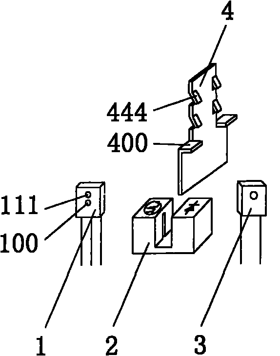
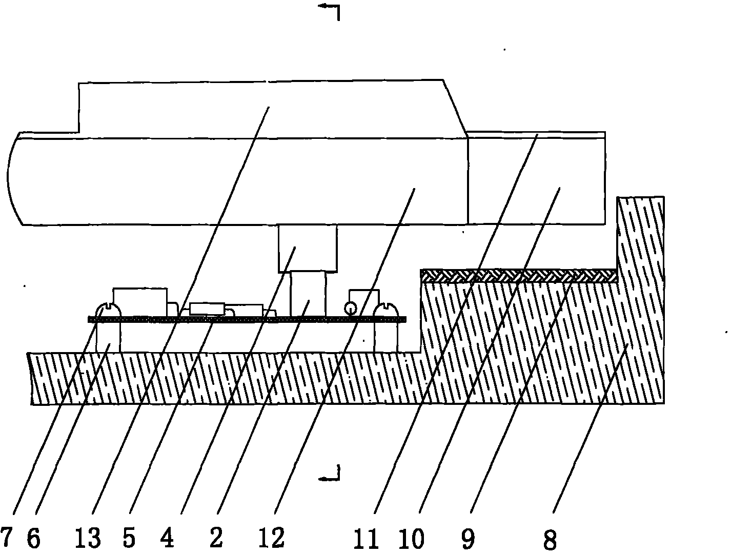
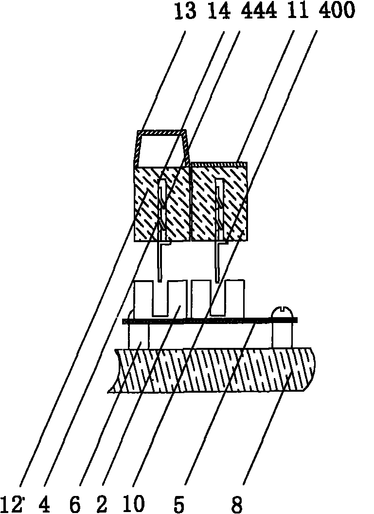
[0016] The technical scheme adopted in the embodiment of the present invention is as follows: Utilize the common preparation process of resin-encapsulated infrared photosensitive transistors, make two identical infrared photosensitive transistor chips on the same electrode bracket, the electrode is the common pole, and the common electrode of the two chips The polarity of each chip is the same, the other electrode of each chip is independent, the two chips are on the same plane, and the centers of the two chips are respectively at the upper and lower positions of the same vertical line. Infrared dual control photosensitive receiving tube of phototransistor. The distance between the two chips is preferably 1 to 2 millimeters, which is an important parameter for force characteristic detection. The dual-control photosensitive receiving tube has one more electrode, and its external dimensions are basically the same as those of ordinary photosensitive receiving tubes. Place the du...


PUM


Abstract

The invention relates to an improved circuit device of an infrared photoelectronic switch, which is used for detecting the key action and playing force of a keyboard musical instrument. The circuit device is characterized in that: two identical phototriode chips manufactured on the same electrode support are packaged into an integrity to be an infrared double-control photo diode by plastic resin, the infrared double-control photo diode and an infrared emitting diode form an infrared double-control photoelectronic switch; each key corresponds to a group of infrared double-control photoelectronic switches and an auxiliary circuit, the keys, the infrared double-control photoelectronic switches and the auxiliary circuit are mutually in electrical connection according to line and row relation to form the matrix scanning circuit of the whole keyboard; and the underside of each key is provided with an infrared photoresist plate, the two phototriodes arranged in the infrared double-control photo diode are cut off or conducted in sequence when the photoresist plate moves up and down along with the key, and a corresponding signal is output to the master control board of an electronic musical instrument after being detected by the matrix scanning circuit. The time interval of the signals output when the two phototriodes are cut off in sequence is detected to calculate the force of playing the keys. Compared with the prior art, the invention has reliability and accuracy, sensitive response, small volume, relatively low cost and strong practicability, and particularly does not influence the playing handfeel of the keys.

Description

[technical field] [0001] The present invention relates to the technical field of musical instruments, in particular to a photoelectric device for musical instrument dynamic keyboards, in particular to a circuit device for detecting keyboard-type musical instrument key action and playing strength through an improved infrared photoelectric switch. [Background technique] [0002] Piano keys have dynamic characteristics, and the key point is that the strength of the fingers playing the keys is positively correlated with the volume effect emitted by the piano. Most electronic pianos and electronic pianos now simulate this force effect of traditional pianos, and the realization principle is based on Newton's second law: the acceleration of an object is proportional to the total external force on the object. That is, by detecting the time difference between two constant points in the movement of the keys, the acceleration and strength can be obtained, and then the volume of the sou...

Claims


Application Information

Patent Timeline
Patent Type & Authority Applications(China)
IPC IPC(8): G10C3/00G10H1/34
Inventor 马季平沈建
Owner SHANGHAI JIUGE MUSIC INSTR
Why Eureka
Try Eureka