
Motor-driven operating mechanism with thermal protector

An electric operating mechanism and protector technology, which is applied to the protection switch operation/release mechanism, the power device inside the switch, etc., can solve the problems of circuit breaker loss, poor size and time control, and burnout of the electric operating mechanism. Small size, saving labor and cost, saving installation space

Inactive Publication Date: 2010-08-04
WUXI KAIXUAN MOTOR
View PDF0 Cites 7 Cited by
  • Summary
  • Abstract
  • Description
  • Claims
  • Application Information

AI Technical Summary

Problems solved by technology

In actual work, the common overcurrent protection device has poor control over the size and time of the electric operating mechanism's overcurrent, because in most cases, the design of the overcurrent protection device of the circuit breaker should consider other electrical equipment such as electromagnetic The starting current of iron, counter, etc. is designed to greatly exceed the normal working current. Therefore, the overcurrent caused by inter-turn short circuit, overload, stalling, etc. of the electric operating mechanism cannot provide good protection, and it is easy to burn out the electric motor. operating mechanisms and circuit breakers resulting in losses

Method used


Image

  • Motor-driven operating mechanism with thermal protector
  • Motor-driven operating mechanism with thermal protector
  • Motor-driven operating mechanism with thermal protector

Examples


Embodiment Construction

[0014] The present invention will be further described below in conjunction with specific drawings and embodiments.

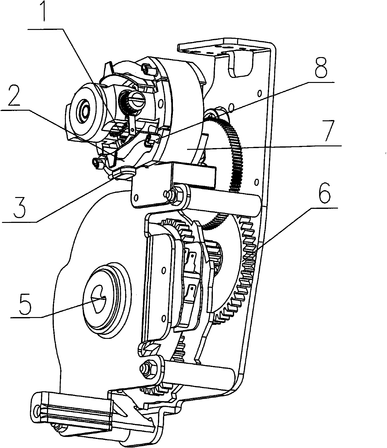
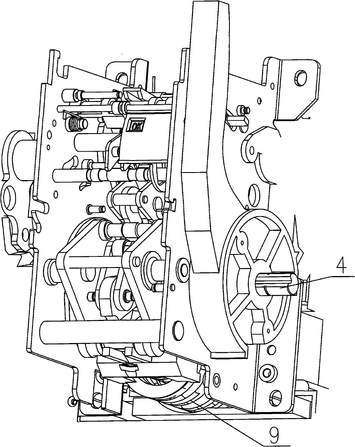
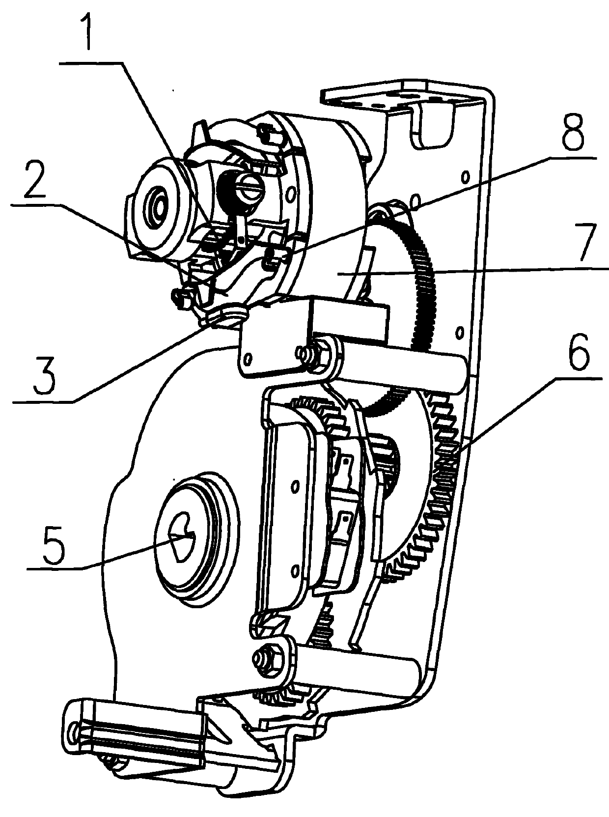
[0015] As shown in the figure: the motor 7 installed in the installation housing, the motor 7 has a motor stator 8 and a motor rotor 1, the motor stator 8 has a stator coil 2, and a reducer 6 and a linkage mechanism are provided in the installation housing, and the reducer 6 It has an output gear 5, the output gear 5 is connected with the main shaft 4 of the circuit breaker, a cam is installed on the main shaft 4 of the circuit breaker, the cam is connected with the linkage mechanism, the output gear 5 of the reducer 6 meshes with the rotor gear of the motor rotor 1, and the A spring 9 is installed in the body, and a thermal protector 3 is installed on the stator coil 2 , and the thermal protector 3 is connected in series with the stator coil 2 .

[0016] A thermal protector 3 (that is, a temperature protector) is connected in series in the circuit of the elect...


PUM


Abstract

The invention relates to a motor-driven operating mechanism, in particular to a motor-driven operating mechanism with a thermal protector. The technical scheme provided by the invention is as follows: the motor-driven operating mechanism comprises a motor installed in an installation shell, wherein the motor is provided with a stator and a rotor; the stator is provided with a stator coil; a speed reducer and a linkage are arranged in the installation shell; the speed reducer is provided with an output gear which is connected with a circuit breaker spindle; a cam is arranged on the circuit breaker spindle and is connected with the linkage; the output gear of the speed reducer is meshed with a rotor gear of the rotor; a spring is arranged in the installation shell; and the thermal protector is arranged on the stator coil and is connected with the stator coil circuit in series. The invention can effectively prevent overcurrent of the motor-driven operating mechanism caused by turn-to-turn short circuit, overload, long idling, locked rotor, etc.

Description

technical field [0001] The invention relates to an electric operating mechanism, in particular to an electric operating mechanism with a heat protector. Background technique [0002] As the core power part of the circuit breaker, the electric operating mechanism is widely used in various circuit breaker industries. Its main function is to convert electrical energy into mechanical energy to provide power for the closing and opening (energy storage) of the circuit breaker. In use, it is generally used to share the overcurrent protection device with the circuit breaker to prevent the motor from burning out due to the temperature of the coil winding in the motor exceeding the allowable value. In actual work, the common overcurrent protection device has poor control over the size and time of the electric operating mechanism's overcurrent, because in most cases, the design of the overcurrent protection device of the circuit breaker should consider other electrical equipment such a...

Claims


Application Information

Patent Timeline
Patent Type & Authority Applications(China)
IPC IPC(8): H01H3/26H01H71/10
Inventor 徐磊汪永峰
Owner WUXI KAIXUAN MOTOR
Learn More