
Miniature stepping motor

A stepping motor, miniature technology, applied in the direction of electrical components, electromechanical devices, electric components, etc., to achieve the effect of simple installation and assembly

Inactive Publication Date: 2011-08-10
彭希南 +1
View PDF0 Cites 0 Cited by
  • Summary
  • Abstract
  • Description
  • Claims
  • Application Information

AI Technical Summary

Problems solved by technology

[0002] The known stepper motor for instrument pointer driving is a digital basic motion device, which uses the output rotating shaft of the motor to drive the instrument pointer. Its main feature is that it does not need position signal feedback to achieve the purpose of position control, and can realize direct conversion of digital signals It can be converted into displacement or speed, and it is allowed to form a servo system in an open-loop control mode. The stepping motor can accelerate, decelerate and stop quickly, and its action has no drift and no accumulated error. Its control characteristics are not affected by load disturbance. Compared with moving magnet or moving coil motors, it completely abandons the working principle of electromagnetic torque-driven pointers, and fundamentally overcomes the shortcomings of traditional analog electromagnetic instruments such as low precision, high failure rate, and short service life. The best replacement product for the digital transformation of the pointer drive mechanism, so it is widely used in the fields of automotive digital instruments and high-reliability industrial measuring instruments

Method used


Image

  • Miniature stepping motor
  • Miniature stepping motor
  • Miniature stepping motor

Examples


Embodiment Construction

[0052] The specific implementation manner of the present invention will be described below in conjunction with the accompanying drawings.

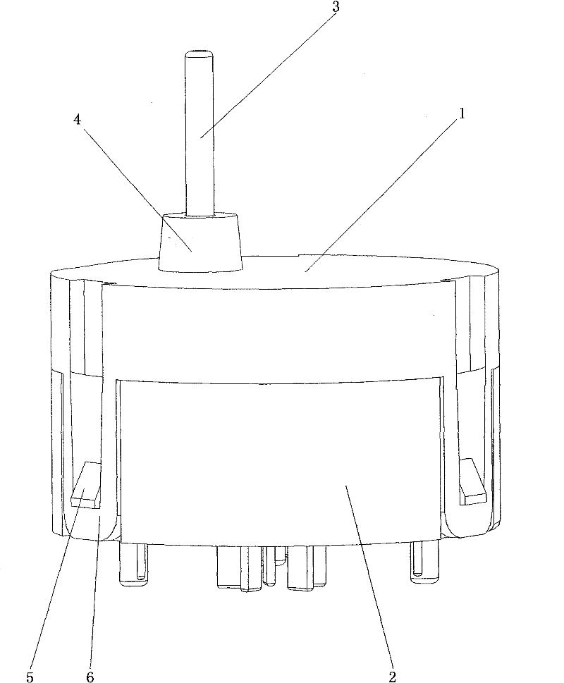
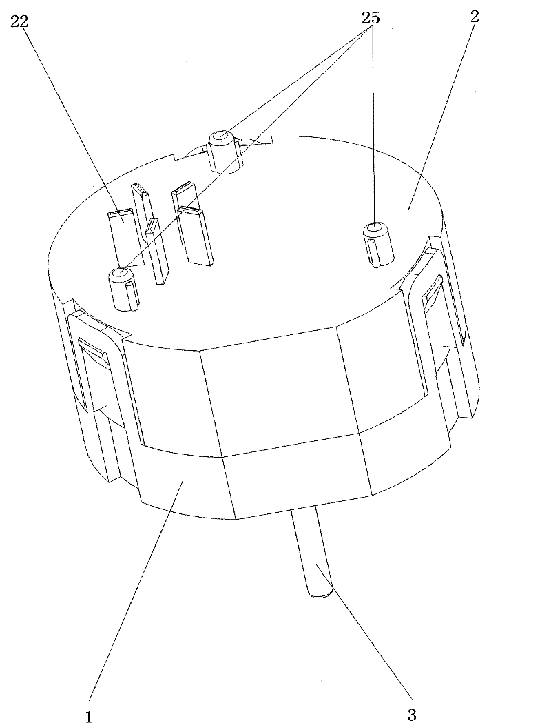
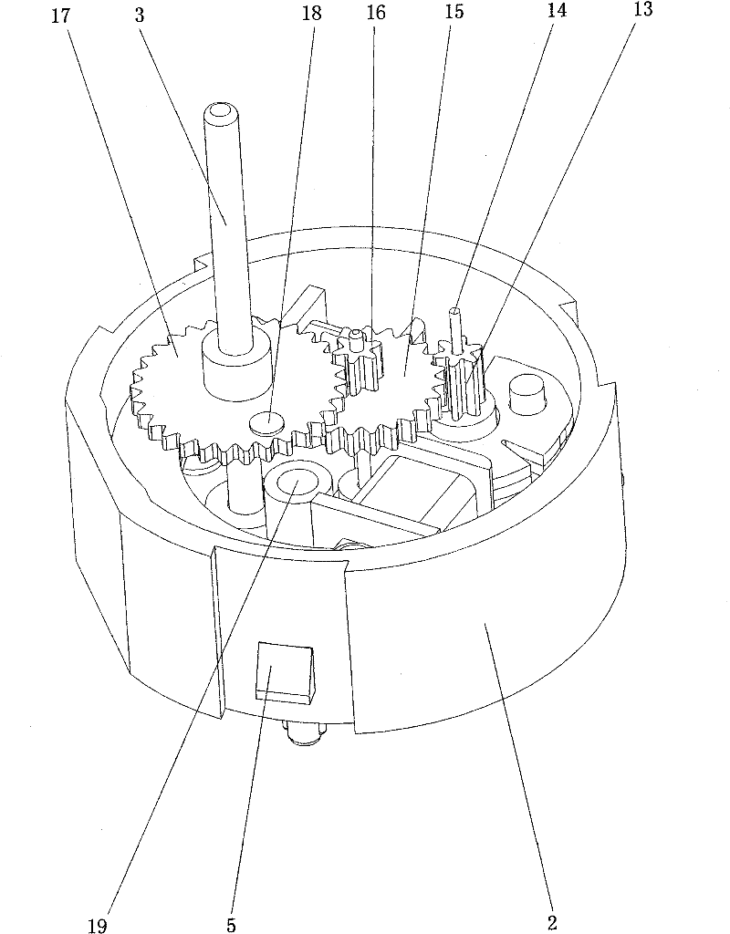
[0053]The present invention includes an upper cover 1, a lower cover 2, a motor output rotating shaft 3, an iron core body 7, a coil bobbin m8, a coil bobbin n9, a rotor body gear 13, a rotor shaft 14, a gear a15, and a gear b16 of the stepping motor. , gear c 17, light guide cylinder 19, PCB board 20, integrated infrared photoelectric tube 23 for transmitting and receiving, and dedicated chip for motor drive 24, wherein the motor output rotating shaft 3 protrudes through the center of the motor output shaft protection step 4 of the upper cover 1 . In terms of assembly, the upper cover 1 and the lower cover 2 adopt a buckle structure. There are three locking hooks 6 on the upper cover 1, and three locking posts 5 on the lower cover 2. When the upper cover 1 and the lower cover 2 are closed, , The three lock hooks 6 on the upper cover 1 re...


PUM


Abstract

The invention discloses a miniature stepping motor with a diameter of 16mm and a thickness of 10mm, which comprises an upper cover, a lower cover, a motor output rotating shaft, an iron core body, a coil framework m, a coil framework n, a rotor body gear, a rotor shaft, a gear a, a gear b, a gear c, a light guide drum, a PCB, an infrared photocell and a chip special for motor drive. The key point of the miniature stepping motor is that: the gear a (15) and the gear b (16) are connected into a whole, the motor output rotating shaft (3) and the gear c (17) are connected into a whole, the gear cluster is connected according to the following engaging transmission relation: the rotor body gear (13) drives the gear a (15), the gear a (15) drives the gear b (16) when rotation, the gear b (16) drives the gear c (17) when rotation, the gear c (17) drives the motor output rotating shaft (3) to rotate, a round light guide drum is arranged on the PCB; an infrared photocell which integrates receiving and transmitting functions is arranged at the bottom of the light guide drum; and both the iron core body and the chip special for motor drive are all fixed on the PCB.

Description

technical field [0001] The invention relates to a miniature stepping motor, in particular to a small-sized stepping motor used to drive the pointer of an instrument to rotate. Background technique [0002] The known stepper motor for instrument pointer driving is a digital basic motion device, which uses the output rotating shaft of the motor to drive the instrument pointer. Its main feature is that it does not need position signal feedback to achieve the purpose of position control, and can realize direct conversion of digital signals It can be converted into displacement or speed, and it is allowed to form a servo system in an open-loop control mode. The stepping motor can accelerate, decelerate and stop quickly, and its action has no drift and no accumulated error. Its control characteristics are not affected by load disturbance. Compared with moving magnet or moving coil motors, it completely abandons the working principle of electromagnetic torque-driven pointers, and f...

Claims


Application Information

Patent Timeline
Patent Type & Authority Patents(China)
IPC IPC(8): H02K37/00H02K7/116H02K11/00H02K11/22
Inventor 彭希南管于球卢文波荀庆来谢稳
Owner 彭希南
Learn More