RF ablation planner

A technology for planning and ablation areas, applied in computer-aided planning/modeling, instruments, calculations, etc., can solve problems such as damage to key areas, patient injuries, etc., and achieve the effect with the shortest duration

Active Publication Date: 2010-08-04
KONINKLIJKE PHILIPS ELECTRONICS NV
View PDF0 Cites 17 Cited by
  • Summary
  • Abstract
  • Description
  • Claims
  • Application Information

AI Technical Summary

Problems solved by technology

Ablation can also damage "critical areas," w

Method used


Image

  • RF ablation planner
  • RF ablation planner
  • RF ablation planner

Examples


Embodiment Construction

[0025] An ablation device, such as an elongated, slender probe, is usually inserted into the tumor, lesion, or other tissue to be ablated, using high radio frequency to heat the tip of the probe in order to heat the surrounding tissue sufficiently to kill cells within it temperature, which is often considered to be 50 degrees Celsius. Although this application primarily describes radiofrequency (RF) ablation techniques that can be used in many sites including the liver, kidneys, chest, lungs, etc., it will be understood that cryoablation, microwave and other ablation and treatments can similarly be used Process planning.

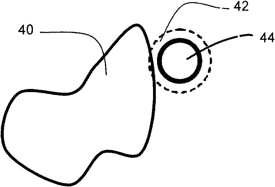
[0026] The ablation zone is usually positioned relative to the probe tip, and is a spheroid or ellipsoid shape, noting that a sphere is an ellipsoid with equal a, b, c axes. When the tumor is larger than the ablation zone for a given probe size, the surgeon selects more than one probe location to create multiple ablation zones that overlap to cover the enti...


PUM


Abstract

In planning an ablation procedure, a planned target volume (PTV) (70, 102) is imported, which is typically selected by a doctor but may be computer identified. An initial set of candidate ablation regions (112) that covers the PTV (40, 70, 102) is computed. Ablation probe trajectories that avoid critical structures (136) are computed to provide surgical 5 options for safe entry points and angles.An optimization component (14) determines a minimum number of ablation regions, which fully covers the PTV (40, 70, 102), and generates locations and orientations for each ablation (108). A tracking system can be given these ablation targets, enabling the surgeon to control the probe more precisely to the desired location.

Description

technical field [0001] This application relates to radiofrequency ablation (RFA), and in particular to the insertion of RF electrode "probes" into a patient so as to cover the intended ablation zone and kill the tumor by increasing its temperature. However, it will be appreciated that the described techniques may also be applied to other ablation techniques, other surgical techniques, and other radiation therapy techniques. Background technique [0002] The probe may be connected to a power source for a predetermined period of time (eg, about 15 minutes, or some other suitable period of time) and ablated in various shapes (but typically a sphere or ellipsoid). Currently, the surgeon can make a mental mark relative to the location of the lesion to be ablated and can utilize various image guides to insert the probe. Because probes are very expensive, surgeons are prevented from using a variety of probe sizes and configurations to support attempts to ablate a mass of tissue us...

Claims


Application Information

Patent Timeline
IPC IPC(8): A61B19/00G06T7/00G06F19/00
CPCG06T2207/30004A61B2019/507A61B19/50A61B2019/504A61B19/5244A61B19/52G06T7/0012A61B34/10A61B34/20A61B90/36A61B2034/104A61B2034/107
Inventor K·I·特罗瓦托D·萨默斯-斯特耶
Owner KONINKLIJKE PHILIPS ELECTRONICS NV
Why Eureka
Try Eureka