Geothermal energy system and method of operation

A technology of geothermal energy and thermal energy, applied in the field of geothermal energy systems, can solve problems such as increased cost, heat energy and pressure loss, and achieve the effects of saving available energy, reducing carbon emissions, and low-carbon emissions.

Inactive Publication Date: 2010-08-04
GREENFIELD MASTER IPCO
View PDF15 Cites 2 Cited by
  • Summary
  • Abstract
  • Description
  • Claims
  • Application Information

AI Technical Summary

Problems solved by technology

This extra ground pipe creates ongoing operational losses such as heat and pressure loss
This in turn requires additional electrical power to cover operational losse

Method used


Image

  • Geothermal energy system and method of operation
  • Geothermal energy system and method of operation
  • Geothermal energy system and method of operation

Examples


Embodiment Construction

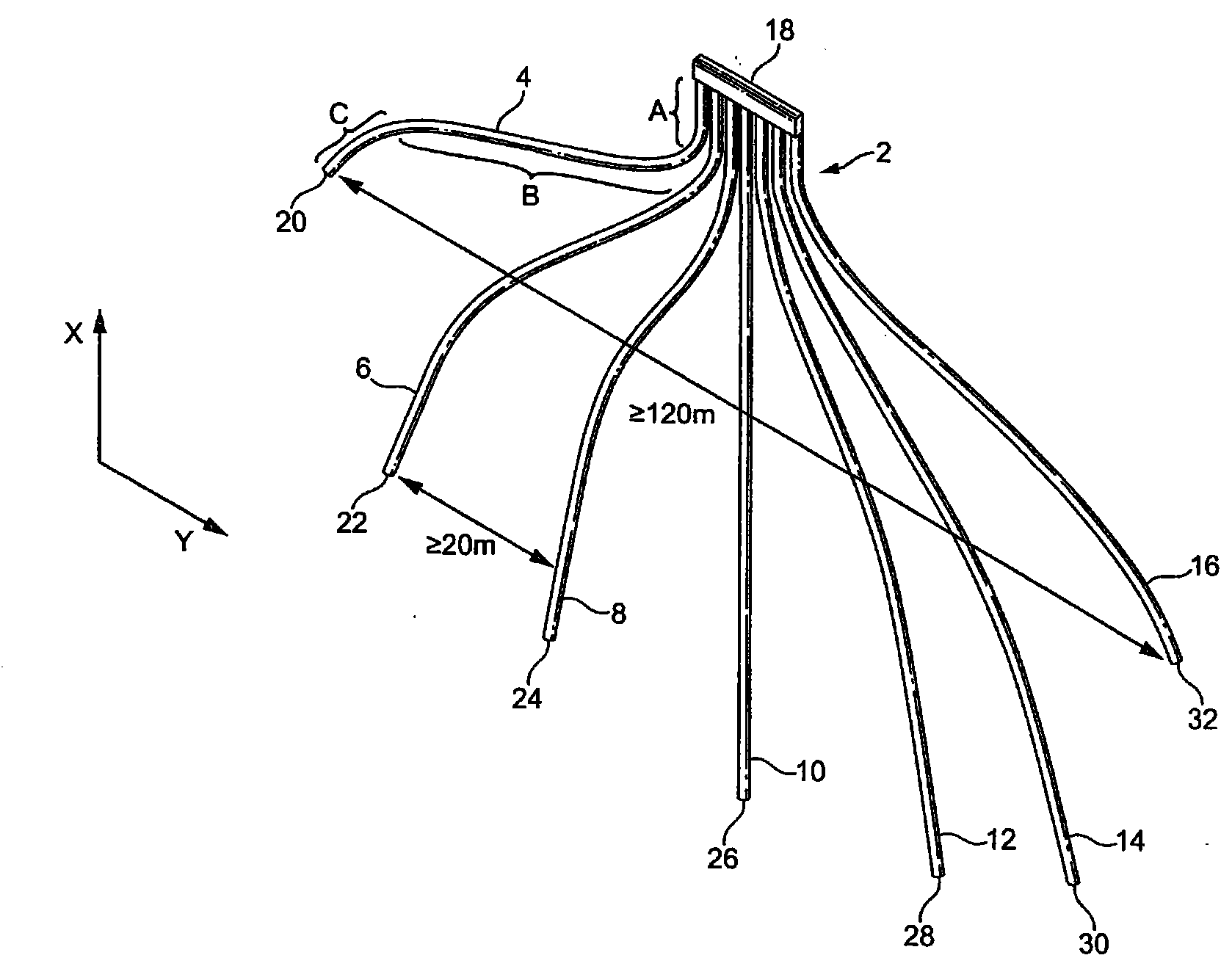
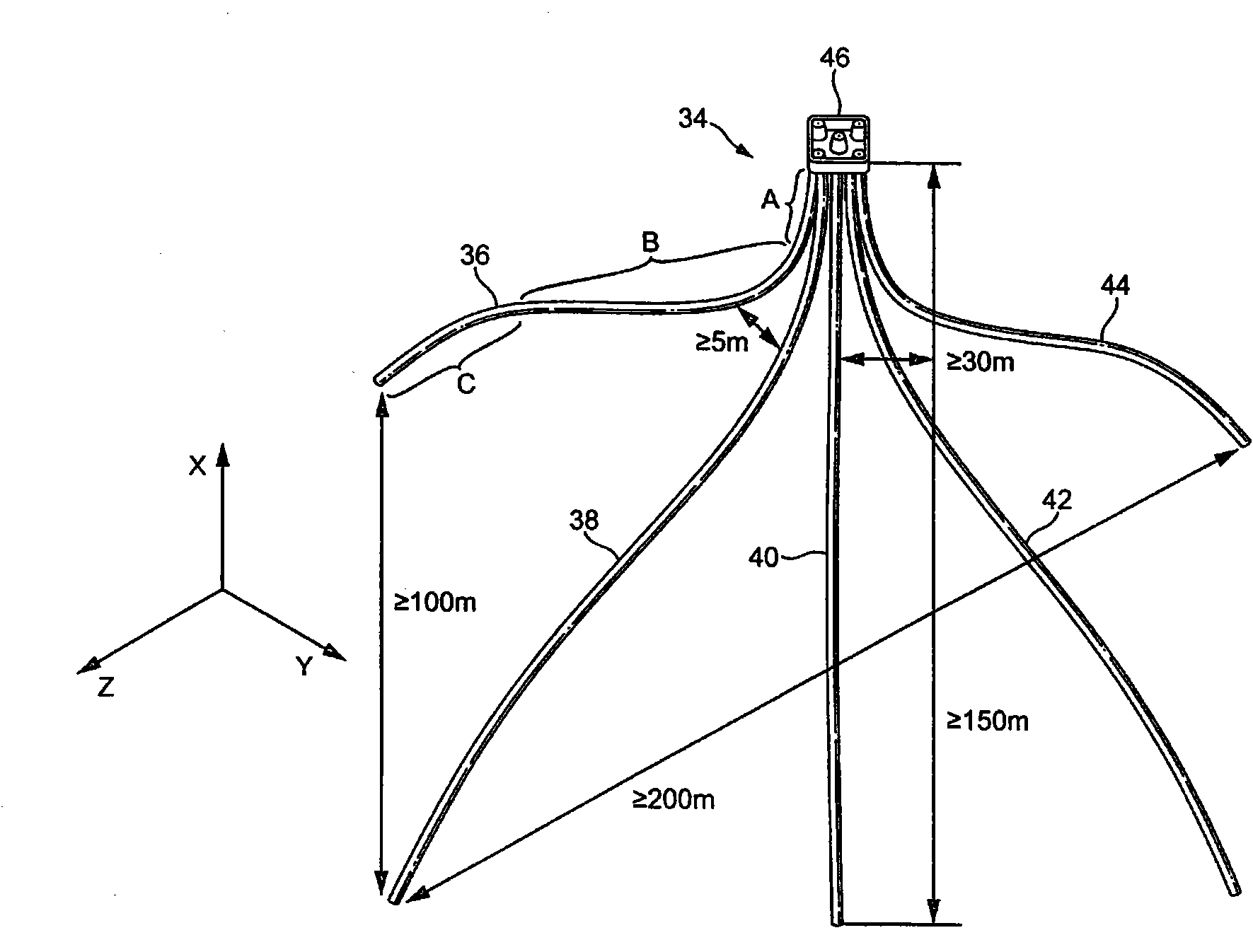
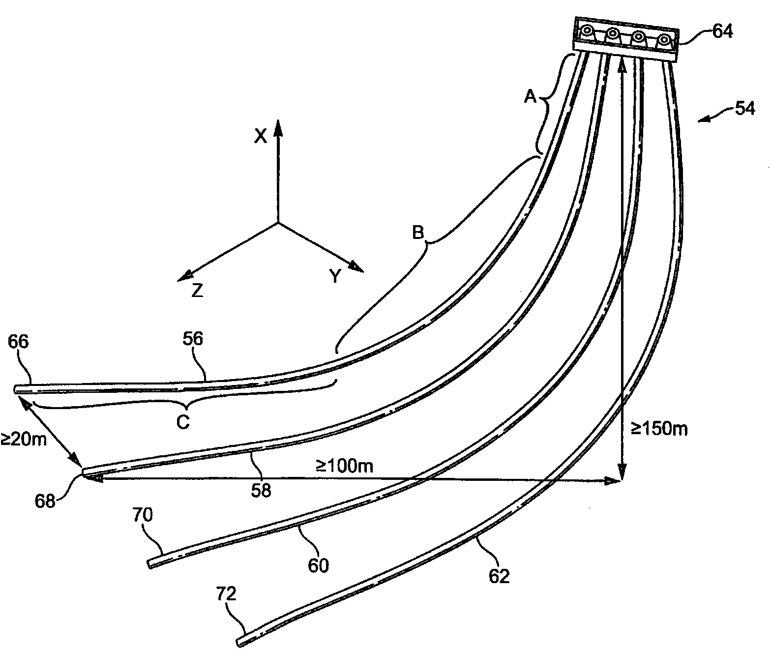
[0088] At the heart of the system of the preferred embodiment of the invention is a compact array or multiple arrays of borehole heat exchangers (BHEs), most preferably coaxial borehole heat exchangers, mounted A rigid structure (preferably concrete) of a building comprising one or more small liners is directionally drilled into a borehole. Depending on whether the primary purpose is to provide heating and / or cooling, borehole heat exchangers can be installed vertically, inclined or horizontally in the formation.

[0089] Optimum cooling is provided by shallow horizontal borehole heat exchangers, optimum heating is delivered by deep vertical borehole heat exchangers, and heat is delivered by borehole heat exchangers inclined at an angle (most often 45 degrees) to the vertical. Heater to provide the best combination of heating and cooling. In addition, depending on the design requirements, a borehole heat exchanger can be divided into two or more branches from some points unde...


PUM


Abstract

A geothermal energy system comprising at least one borehole heat exchanger, Hie at least one borehole heat exchanger containing a working fluid and comprising an elongate tube having a closed bottom end and first and second adjacent elongate coaxial conduits interconnected at the bottom end, the first conduit being tubular and surrounded by the second conduit which is annular, the at least one borehole heat exchanger having a major portion thereof extending in a substantially inclined orientation at an angle of from 3 to 95 degrees from vertical.

Description

technical field [0001] The invention relates to a geothermal energy system and also to a method of operating a geothermal energy system. Background technique [0002] For more than a century, geothermal energy has been used around the world in various forms for electricity generation and direct heating. Typically, these devices are located in volcanically active regions where high-enthalpy source rocks are relatively close to or at the Earth's surface, such as the western United States, Iceland, or the Philippines. Lesser known but of increasing importance in recent decades has been the application of low-enthalpy geothermal resources such as low-temperature turbine generators and the use of ground-source heat pumps (GSHP) for heating, cooling and heat storage development has been achieved. [0003] The basic principle involved takes advantage of the stable thermal conditions that exist in the formation below about 10 meters below the surface. This stability comes from th...

Claims


Application Information

Patent Timeline
IPC IPC(8): F03G7/04F24D11/02F24J3/08
CPCY02E10/16F24J3/086F03G7/04Y02B10/40F24T10/30Y02E10/10F24T2010/56F24T2201/00F24T10/40F24D11/02
Inventor 詹姆斯·J·斯图尔特德米特里·I·扎耶努林安东尼·C·斯科特格雷厄姆·牛顿
Owner GREENFIELD MASTER IPCO
Why Eureka
Try Eureka