Tool holder

A tool holder, tool technology, used in the manufacture of tools, metal processing, accessories for tool holders, etc.

Inactive Publication Date: 2010-08-11
FRANZ HAIMER MASCHINENBAU KG
View PDF5 Cites 3 Cited by
  • Summary
  • Abstract
  • Description
  • Claims
  • Application Information

AI Technical Summary

Problems solved by technology

However, especially when trying to automate the tool change, problems can arise when handling the screw sleeves of the known tool holders

Method used


Image

  • Tool holder
  • Tool holder
  • Tool holder

Examples


Embodiment Construction

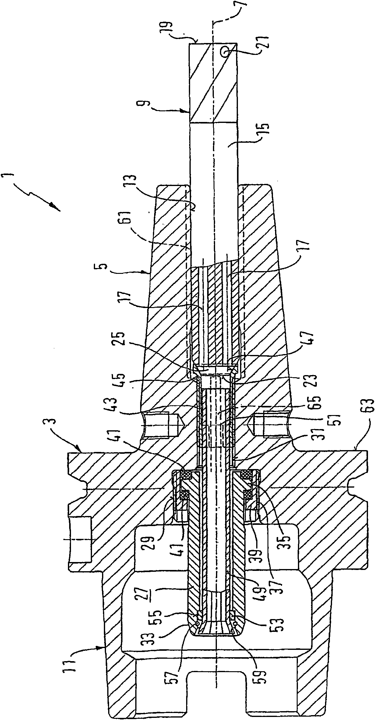
[0044] figure 1 Indicates a tool holder of the shrink chuck type, which is usually a one-piece clamp body 3 with a sleeve-shaped tool mounting section 5 at one axial end of the clamp body 3 for a drive to be rotated about an axis of rotation 7 A tool 9, such as a milling cutter or a drill bit, and at the axially opposite end there is an engaging section 11 in the form of a hollow rod adapter here, for torque-proof connection with the rotary drive shaft of the machine tool, which is not shown in detail here. join. The mounting section 5 has a mounting hole 13 concentric to the axis of rotation 7, which can be thermally expanded by means of an induction coil, in particular by induction heating, so that the tool 9 can be inserted loosely with its shank 15 into the mounting hole 13 or removed from it. After the mounting section 5 has cooled, the tool shank 15 is press-fitted into place.

[0045] A plurality of, here two, axial channels 17 parallel to the axis of rotation 7 exten...


PUM


Abstract

The present invention relates to a tool holder. The aim of the utility model is to improve the guiding of lubricant in a system with small lubricant amount through the tool holder. Thus the invention provides the tool holder (1) which comprises an axially displaceable stop sleeve (45) in a through opening (31) which is connected to the receiving opening ( 13 ) for a tool shaft ( 15 ) in a holder body (3). The stop sleeve abuts against an end (23) of a tool shaft (15) through a stop surface (47). The invention requests that: the stop sleeve (45a, b, d-i) comprises a spring (67a,b,d-i) which pretighens the stop surface (47a, b, d-i) to the end (23a, b, d-i) of the tool shaft (15a, b, d-i). The tool holder (1) can feed the lubrication fluid to the tool (9) basically without eddy at a state with small lubrication amount, and simplifies the length pre-adjustment of the tool-tool holder assembly.

Description

[0001] This application is a divisional application of the Chinese invention patent application with the application number "200680004908.3". The filing date of the original application is March 22, 2006 (the PCT international filing date), the application number is "200680004908.3" (the PCT international filing number is PCT / EP2006 / 002637), and the name of the invention is "tool fixture". technical field [0002] The invention relates to a tool holder, in particular to a tool holder for a tool to be driven in rotation about an axis of rotation, the tool shank comprising at least one channel for cooling and / or lubricating fluid extending along the axis of rotation, or with Together, the tool holders form the boundaries of their channel cross-sections. Background technique [0003] It is known that for cooling or lubricants to be supplied to the cutting edges of rotating cutting tools (cutters) such as drills or milling cutters in the form of liquid jets or as sprays, they ar...

Claims


Application Information

Patent Timeline
Patent Type & Authority Applications(China)
IPC IPC(8): B23B31/02B23B31/30B23P11/02B23Q11/10B23Q17/22
CPCB23B2231/24B23Q11/1015B23B31/028B23B31/1179B23Q11/1023Y10T279/1021Y10T279/1249Y10T279/17957Y10T408/44Y10T408/95Y10T409/304032Y10T409/30952
Inventor F·海默B·雷高
Owner FRANZ HAIMER MASCHINENBAU KG
Why Eureka
Try Eureka