High pressure discharge lamp

A high-pressure discharge lamp and electrode technology, which is applied in discharge lamps, gas discharge lamps, discharge tubes, etc., can solve problems such as fusing, and achieve the effects of preventing mandrel from bending, preventing bending, and suppressing fusing

Inactive Publication Date: 2012-07-04
USHIO DENKI KK
View PDF1 Cites 0 Cited by
  • Summary
  • Abstract
  • Description
  • Claims
  • Application Information

AI Technical Summary

Problems solved by technology

In addition, it is known from prior experience that the terminal end of the mandrel 7 will also bend toward the metal foil 6 side.
The metal foil 6 is heated due to the increase of the electric load, and then compressed due to the bending of the mandrel 7, thereby causing melting

Method used


Image

  • High pressure discharge lamp
  • High pressure discharge lamp
  • High pressure discharge lamp

Examples


Embodiment Construction

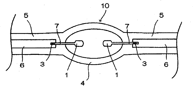
[0023] figure 1 It is a partial enlarged view showing the structure of the high-pressure discharge lamp 10 of the first embodiment.

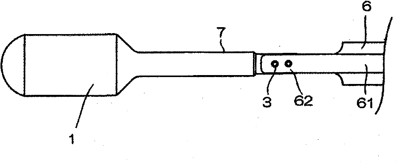
[0024] The high-pressure discharge lamp 10 has a substantially spherical light-emitting portion 4 made of quartz glass, in which an electrode 1 made of tungsten is arranged opposite. Also, a sealing portion 5 is formed so as to protrude from the end of the light emitting portion 4 , and a conductive metal foil 6 made of, for example, molybdenum is embedded in the sealing portion 5 in an airtight manner by shrink sealing. The pair of electrodes 1 is composed of a large-diameter front end and a thin-diameter mandrel 7 , and the mandrel 7 is welded to the metal foil 6 and electrically connected.

[0025] Mercury, a rare gas, and a halogen are enclosed in the light emitting unit 4 .

[0026] The amount of mercury is enclosed with 0.15mg / mm 3 Above, in order to obtain the necessary wavelength of visible light, for example, radiated light with a w...


PUM


Abstract

To provide a high pressure discharge lamp in which no fusing of the metal foil (6) occurs even if the high pressure discharge lamp is switched on for a certain time a high pressure discharge lamp is provided having a discharge vessel comprised of a light emission part (4) and sealing parts (5) made of glass connected to opposite ends of said light emission part (4); metal foils (6) buried in a respective one of said sealing parts (5); a pair of electrodes (1) comprised of core rods (7) and tip end parts, said tip end parts being arranged oppositely to each other in the light emission part (4); and said core rods being melted and fused together with a respective one of the metals foils; wherein cavities (2) are formed which reach from a surface of a respective one of the metal foils (6) toan interior of the core rod (7), and the glass constituting said sealing part (5) has entered into said cavities (2).

Description

technical field [0001] The present invention relates to high pressure discharge lamps used in digital projectors or liquid crystal projectors, DLP (Digital Light Processing) projectors and the like. Especially related to the sealing of 0.15mg / mm in the light emitting part 3 High-pressure discharge lamps with mercury vapor pressure above 110 atmospheres. Background technique [0002] In recent years, liquid crystal projectors and DLP projectors using digital light processing technology have become popular. The light source for image projection is a short-arc high-pressure discharge lamp. [0003] Figure 5 It is a partial cross-sectional view showing the structure of the high-pressure discharge lamp 10 disclosed in JP-A-2004-363014. [0004] The high-pressure discharge lamp 10 has a discharge vessel formed of a spherical light emitting portion 4 formed in the center and sealing portions 5 formed at both ends of the light emitting portion 4 . A pair of electrodes 1 are dis...

Claims


Application Information

Patent Timeline
Patent Type & Authority Patents(China)
IPC IPC(8): H01J61/073F21Y101/00
CPCH01J5/38H01J61/36H01J9/36H01J61/366
Inventor 笠石朱贵梅崎悟向野阳一
Owner USHIO DENKI KK
Why Eureka
Try Eureka