Brush-type spraying device for concrete sprayers

A technology of concrete spraying machine and spraying device, which is applied in the direction of spraying device, liquid spraying device, shaft equipment, etc., which can solve the problems of low construction efficiency, low concrete utilization rate, and negative impact on the health of construction workers, so as to improve the utilization rate and work efficiency, the spray direction is easy to control, and the effect of reducing the possibility of collapse

Inactive Publication Date: 2010-08-18
上海鸿得利重工有限公司
View PDF4 Cites 26 Cited by
  • Summary
  • Abstract
  • Description
  • Claims
  • Application Information

AI Technical Summary

Problems solved by technology

[0004] The initial support lining of early tunnel New Austrian method construction adopts the concrete dry spraying construction technology, which has the characteristics of simple process, poor equipment, serious dust pollution, low concrete strength, difficult control of water-cement ratio, and large rebound rate, which not only leads to The utilization rate of concrete is low, the construction efficiency is not high, and more importantly, the quality of the project is difficult to meet the design requirements, which has a great negative impact on the health of construction workers

Method used


Image

  • Brush-type spraying device for concrete sprayers
  • Brush-type spraying device for concrete sprayers
  • Brush-type spraying device for concrete sprayers

Examples


Embodiment 1

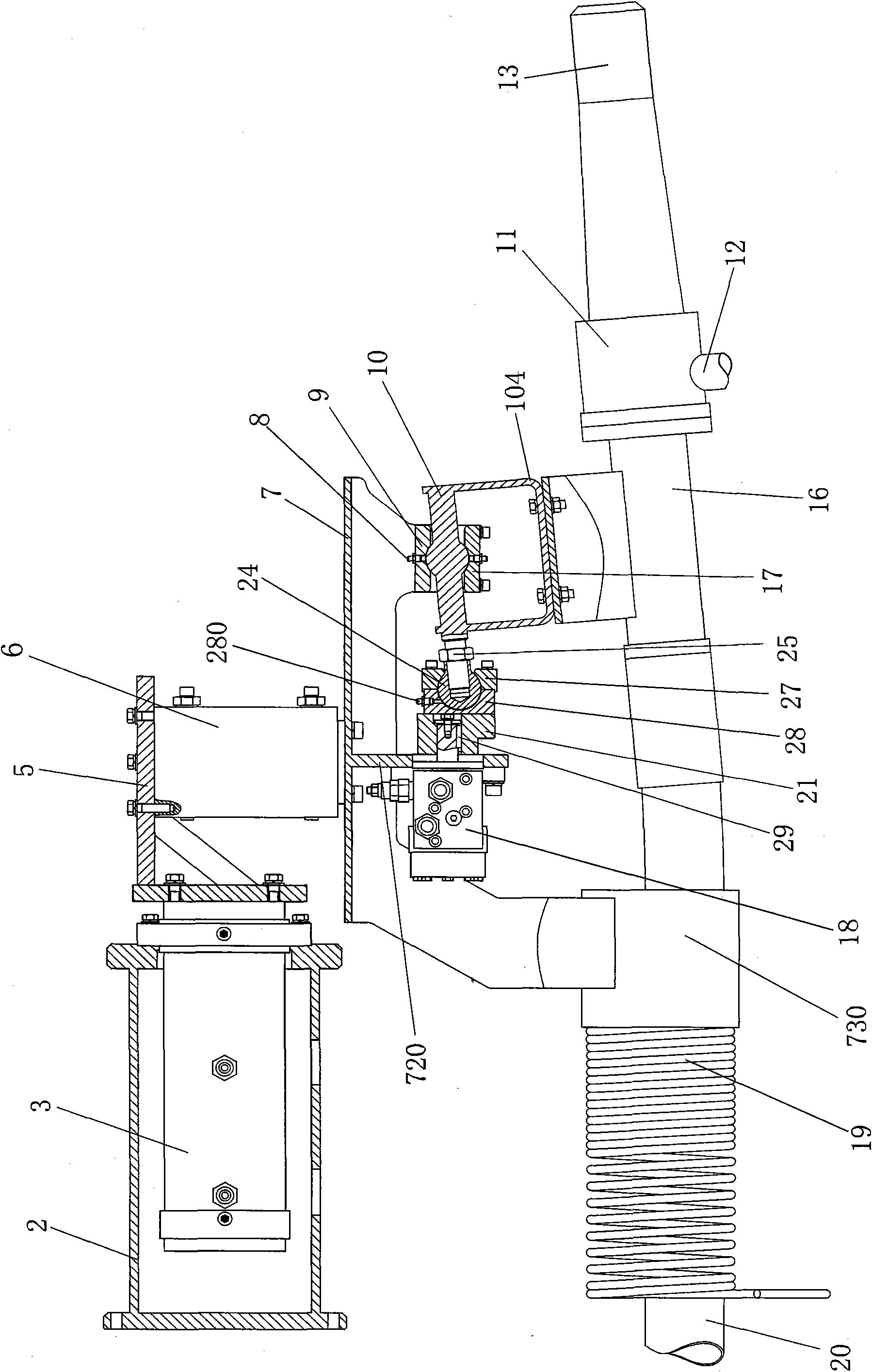
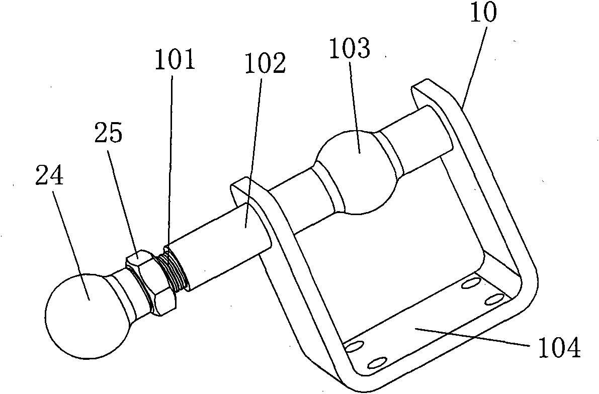
[0040] Such as figure 1 , figure 2 , image 3 The joint bearing of this embodiment includes a ball sleeve fixed body 28 connected to the eccentric disc 21, a ball sleeve 24 located in the ball sleeve fixed body 28 and connected with the extended end of the swing shaft 102, used for fixing the ball sleeve 24 and connecting with the ball The ball sleeve fixing cover 27 connected with the sleeve fixing body 28 is provided with a ball sleeve lubricating assembly 280 on the ball sleeve fixing body 28 . The ball socket fixed body 28 is integrated with the ball socket fixed cover 27 to form a ball joint overcoat. The protruding end of the swing shaft 102 is a threaded section 101 , and the ball sleeve 24 and the threaded section 101 are fixed by a locking nut 25 .

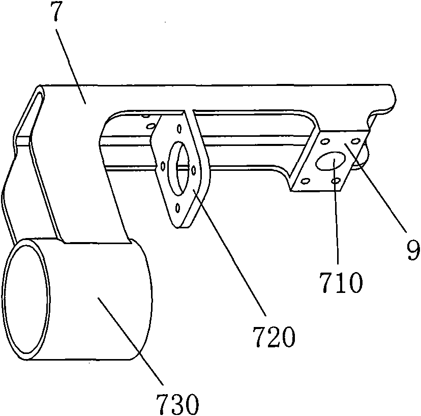
[0041] The spherical hinge structure of this embodiment includes a spherical protrusion 103 arranged on the swing shaft 102, a spherical crown-shaped recess 710 arranged on the hinge seat 9 of the brush frame, and a s...

Embodiment 2

[0044] Such as Figure 4 , Figure 5 , Image 6 In this embodiment, the joint bearing includes a ball joint rod 214 fixed on the eccentric disk 21 and a dimple 105 provided on the protruding end of the swing shaft 102 . The ball head of the ball joint rod 214 is located in the dimple 105 . Of course, in this example, the ball head lever 214 can also be arranged on the protruding end of the swing shaft 102 , and the pit 105 can be arranged on the eccentric disk 21 .

[0045] All the other structures are the same as in Embodiment 1.

Embodiment 3

[0047] Such as Figure 7 , Figure 8 , the ball hinge structure of this embodiment includes a spherical step hole 106 arranged on the swing shaft 102, a ball-end boom 31 fixed on the hinge seat 9 of the brush frame, and the ball head of the ball-end boom 31 is located on the spherical step Inside the hole 106.

[0048] All the other structures are the same as in Embodiment 1.


PUM


Abstract

The invention relates to a brush-type spraying device for concrete sprayers. The brush-type spraying device comprises a hollow cylindrical spraying device mounting seat 2, a first hydraulic motor 3, a second hydraulic motor 6 and a third hydraulic motor 18, wherein the first hydraulic motor 3 is installed in the cavity of the spraying device mounting seat 2; the first hydraulic motor 3 is connected with the second hydraulic motor 6 through a right-angled mounting rack 5, and the second hydraulic motor 6 is connected with a spraying nozzle mounting rack 7; the spraying nozzle mounting rack 7 is provided with a third motor seat 720 and a brush rack hinged support 9; the protruding end of a swing axle 102 is connected with the output shaft of the third hydraulic motor 18 through an eccentric disc 21 and a knuckle bearing, and the swing axle 102 is connected with the brush rack hinged support 9 through a ball joint structure; and a concrete delivery hard pipe 16 is fixed on a brush rack 10. The invention has the advantages of reducing the resiliency and the slump of concrete spraying, increasing the utilization ratio of the concrete, improving the tunnel construction environment, enhancing the concrete spraying quality and the like.

Description

technical field [0001] The invention relates to a spraying device applied to a concrete spraying machine, and in particular discloses a brush-type spraying device for a concrete spraying machine. Background technique [0002] There are two major theories in tunnel design and construction: one is relaxation load theory, the core content of which is that stable rock mass has self-stabilization ability and does not generate load, while unstable rock mass may collapse and needs to be supported by supporting structures. The load acting on the support structure in this way is the rock mass force of the surrounding rock due to relaxation and possible collapse within a certain range; the second is the rock bearing theory, the core content of which is that the stability of the surrounding rock is obviously the self-stabilizing capacity of the rock mass itself. , there is a process for unstable surrounding rocks to lose their stability. If necessary restrictions are provided during th...

Claims


Application Information

Patent Timeline
Patent Type & Authority Applications(China)
IPC IPC(8): E21D11/10B05B7/14
Inventor 徐沛良胡小其
Owner 上海鸿得利重工有限公司
Why Eureka
Try Eureka