
Cooling device with bottle cooling function

A refrigeration appliance and cooled technology, which can be used in household refrigeration devices, cooling fluid circulation devices, household appliances, etc., and can solve problems such as bottle bursts

Inactive Publication Date: 2010-08-18
BSH BOSCH & SIEMENS HAUSGERAETE GMBH
View PDF8 Cites 13 Cited by
  • Summary
  • Abstract
  • Description
  • Claims
  • Application Information

AI Technical Summary

Problems solved by technology

However, the problem that arises in this case is that the user has to remove the bottle again at the correct time in order to avoid supercooling of the contents of the bottle
If the necessary cooling time is significantly exceeded, the contents of the bottle can freeze and thus cause the bottle to burst

Method used


Image

  • Cooling device with bottle cooling function
  • Cooling device with bottle cooling function
  • Cooling device with bottle cooling function

Examples


Embodiment Construction

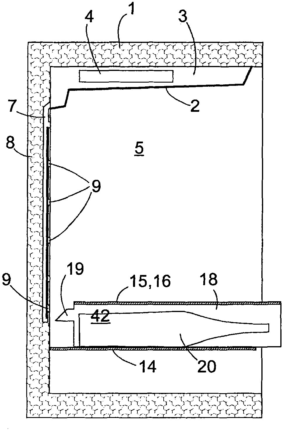
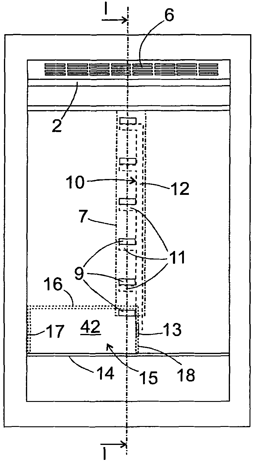
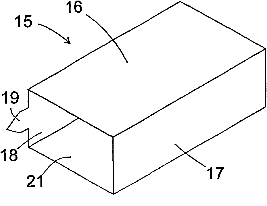
[0034] figure 1 Shows the main body of the refrigeration appliance constructed according to the principle of no frost, along figure 2 Sectional view along the cutting plane indicated by line I-I in the front view of the body shown. The inner space of the body is divided in known manner by a shell 2 mounted under the cover 1 of the body into an evaporator chamber 3 with an evaporator 4 and a blower (not shown) and a storage area 5 for refrigerated items. From the storage area 5 through the opening 6 on the front side of the shell 2 (see figure 2 ) is cooled on the evaporator 4 and discharged from the evaporator chamber 3 by means of the duct 7, which extends in the rear wall 8 of the body and has a plurality of channels leading back into the storage area 5 exit 9. Depend on figure 2 A grid-shaped control element 10 , shown in dashed outline in the front view of , extends in the interior of the conduit 7 . The plate-shaped fingers 11 of the control element 10 are located...


PUM


Abstract

A cooling device has an evaporator (24) and a storage area (5) cooled by air flowing along an evaporator (4). A flow path of the air runs downstream from the evaporator (24) extends through a compartment (42) partitioned from the storage area (5).

Description

technical field [0001] The invention relates to a refrigerating appliance suitable for rapidly cooling beverage bottles, especially a household refrigerating appliance. Background technique [0002] With conventional refrigeration appliances, the user has various options for cooling bottles containing beverages. In most home refrigerators, the space for beverage bottles is provided in the door bottle rack. If the user places a 0.7 liter wine bottle at a temperature of 25°C in this door bottle rack, it will take about 4 hours to cool the bottle and its contents below 10°C. A reduced time of about 120 minutes can be achieved in circulating air refrigerated appliances, where cool air is forced to circulate by means of a blower, or by placing the bottle next to an evaporator mounted generally on the rear wall of the appliance. [0003] Even shorter cooling times are possible if the bottles are housed in a freezer. In this case, the bottle can be cooled from 25°C to 10°C in ab...

Claims


Application Information

Patent Timeline
IPC IPC(8): F25D23/12F25D17/06F25D17/04F25D29/00
CPCF25D2317/061F25D17/062F25D2317/067F25D2331/803F25D31/007F25D2400/28
Inventor P·纳尔巴赫S·舍希钦格尔周小天
Owner BSH BOSCH & SIEMENS HAUSGERAETE GMBH
Learn More