
T-shaped flow meter

A flowmeter and flow measurement technology, applied in volume measurement, liquid/fluid solid measurement, measurement device and other directions, can solve the problems of reducing measurement accuracy, transmission signal fluctuation, consumption of fluid energy, etc., to achieve stable and reliable operation, easy installation and use , the effect of high measurement accuracy

Inactive Publication Date: 2012-01-18
林福成 +1
View PDF0 Cites 1 Cited by
  • Summary
  • Abstract
  • Description
  • Claims
  • Application Information

AI Technical Summary

Problems solved by technology

Since the flow measuring element of the target flowmeter adopts a flat and thin circular plate, when the fluid flows through the flow measuring element, a vortex will be generated behind the flow measuring element, which will cause the vibration of the flow measuring element, fluctuate the transmission signal, and reduce the measurement precision
Moreover, the vortex can also convert kinetic energy into heat energy, causing large pressure loss and consuming fluid energy.
In recent years, although the manufacturers have made many improvements in the force conversion of the target flowmeter, they have failed to improve the shape and structure of the flow measuring element, resulting in the above-mentioned defects still existing and restricting its development.

Method used


Image

  • T-shaped flow meter
  • T-shaped flow meter
  • T-shaped flow meter

Examples


Embodiment 1

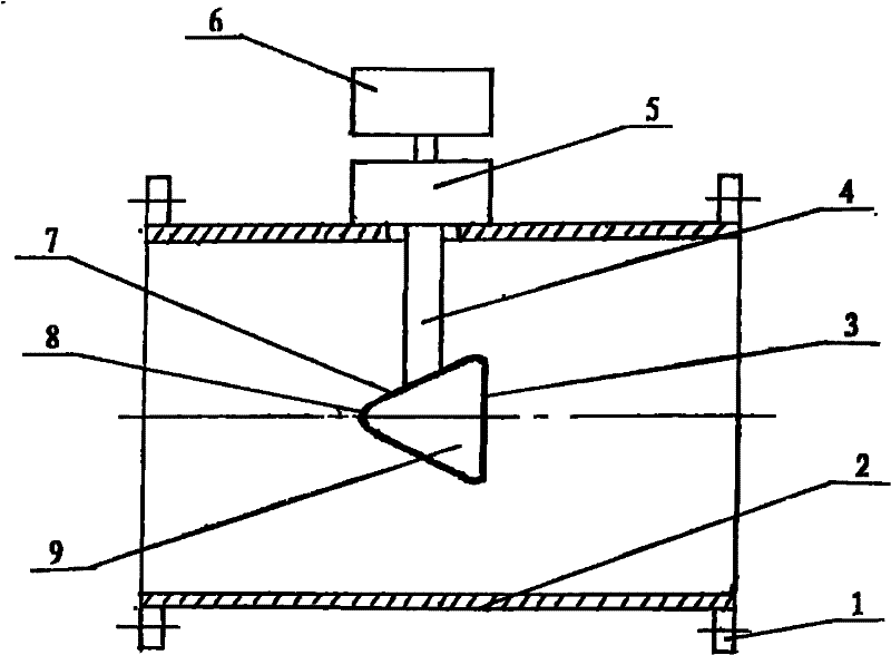
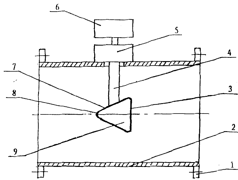
[0011] figure 1 Among them, a T-shaped polyhedron flow measuring element 9 is arranged in the middle of the measuring tube 2 with an inner diameter of 300mm, and the flow measuring element 9 is connected with the conversion unit 5 arranged outside the measuring tube 2 through the force rod 4 connected thereto, and the conversion unit 5 and The computing display unit 6 is connected. And the measuring pipe 2 is connected with the process pipeline flange through the flange 1 connected therewith, which is convenient for on-site installation and disassembly. The upstream surface 3 of the T-shaped polyhedron flow measuring element 9 is a plane with an outer diameter of 100mm, and the downstream surface 7 is a cone, the outer surface of which is a slope, and the cone angle is 60°. The top is a hemisphere 8 that is smoothly connected with the cone and has a radius of 20mm. The flow measuring element 9 is made of plastic sprayed or covered with corrosion-resistant materials; it can a...

Embodiment 2

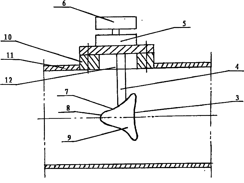
[0014] figure 2 Among them, the upstream surface 3 of the T-shaped polyhedron flow measuring element 9 is a concave arc surface, the downstream surface 7 is a cone, and its outer surface is a concave arc surface, and the top of the downstream surface 7 is smoothly connected with the cone. hemisphere8.

[0015] figure 2 What is shown is a plug-in connection structure between the T-shaped polyhedron flow measuring element 9 and the measuring tube, which is suitable for installation and use during equipment overhaul in existing pipelines. The specific connection method is: the process pipeline 11 is used as the measuring tube of the flowmeter, a rectangular groove is arranged on the pipeline wall of the process pipeline 11 along the pipeline axial direction, and a base 10 is fixedly connected to the pipeline wall at the position of the groove, There is a central hole 12 in the base 10 through which the T-shaped polyhedron flow measuring element 9 can pass. When the T-shaped ...


PUM


Abstract

The invention relates to a T-shaped flow meter, which is mainly characterized in that a flow measuring element arranged in a measuring pipe is a T-shaped polyhedron which is connected with a computation display unit through a conversion unit. The flow meter can effectively eliminate vortex generated when fluid flows through the flow measuring element and adhesion of dirty fluid, and has the characteristics of stable and reliable work, little pressure loss, high measurement precision, firmness and durability and convenient use and installation. The invention can be used for measuring various fluid media, such as gas, liquid, steam, double-phase fluid, smudge, thick fluid, high-temperature fluid, high-pressure fluid, wear fluid, corrosive fluid, and the like, and for measuring flow of various circular pipes or square pipes with large diameter, medium diameter and small diameter.

Description

technical field [0001] The invention relates to a fluid flow measuring instrument, especially a T-shaped flow meter. It is suitable for flow measurement of various fluids. Background technique [0002] Flow measuring instrument is a widely used automatic instrument. At present, the flow measuring instruments manufactured by the principle of fluid mechanics include: throttling devices, uniform velocity tube flowmeters, target flowmeters, elbow flowmeters, etc. Among them, the target flowmeter is composed of a measuring tube and a flat and thin disc type flow measuring element arranged in the measuring tube. Since the flow measuring element of the target flowmeter adopts a flat and thin circular plate, when the fluid flows through the flow measuring element, a vortex will be generated behind the flow measuring element, which will cause the vibration of the flow measuring element, fluctuate the transmission signal, and reduce the measurement precision. Moreover, the vortex ...

Claims


Application Information

Patent Timeline
Patent Type & Authority Patents(China)
IPC IPC(8): G01F1/20G01F15/00
Inventor 林福成邵朋诚
Owner 林福成
Learn More