Unlock instant, AI-driven research and patent intelligence for your innovation.

Locating method of emitting source

A positioning method and emission source technology, applied in positioning, measuring devices, instruments, etc., can solve problems such as inability to guarantee simulated sound sources and actual sound sources, cumbersome acoustic emission source positioning work, and acoustic emission source positioning errors, etc. Positioning formula, convenient application, the effect of eliminating positioning error

Inactive Publication Date: 2010-08-18
SHENYANG INSTITUTE OF CHEMICAL TECHNOLOGY
View PDF2 Cites 15 Cited by
  • Summary
  • Abstract
  • Description
  • Claims
  • Application Information

AI Technical Summary

Problems solved by technology

In practice, in order to obtain the calculation equation of the location of the acoustic emission source and simplify the calculation, the location of the receiver of the acoustic emission signal (hereinafter referred to as the sensor) is usually arranged according to a specific regular geometric figure. According to the geometric figure of the sensor arrangement, the time difference positioning The method can be divided into square positioning method, equilateral triangle positioning method and spherical triangle positioning method, etc., but the calculation formula for determining the position of the acoustic emission source derived from the above-mentioned various methods is still relatively cumbersome, which makes the positioning of the acoustic emission source more cumbersome; in addition , in the past time difference localization method needs to measure the speed of the sound wave with the simulated sound source in advance, but because the frequency of the simulated sound source and the actual sound source cannot be guaranteed to be completely consistent, it has been proved that even if it is the same medium, as long as its geometric shape Different, even the same acoustic emission source will have different sound wave propagation speed, therefore, the method of using the simulated sound source to determine the sound wave propagation speed in the medium in advance will bring errors to the location of the acoustic emission source

Method used


Image

  • Locating method of emitting source
  • Locating method of emitting source
  • Locating method of emitting source

Examples


Embodiment

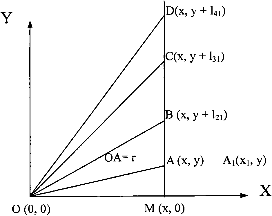
[0018] Example: see figure 1 As shown, in the plane Cartesian coordinate system XOY, the coordinate origin O is the source of acoustic emission, and the Y axis is parallel to the straight line AD. l 21 ), C(x,y+l 31 ), D(x,y+l 41 ), let OA=r, OB=r+r 21 , OC=r+r 31 , OD=r+r 41 . The time difference between the sound waves emitted from the sound source O(0,0) arriving at the sensors at B, C, and D relative to the sensor at A is t 21 , t 31 and t 41 . If the propagation velocity of the sound wave is v, then r 21 =vt 21 、r 31 =vt 31 、r 41 =vt 41 .

[0019] The point M(x, 0) is the intersection point of the X-axis and the straight line AD, and the triangles MOA, MOB, MOC, and MOD are all right-angled triangles. According to the Pythagorean theorem:

[0020] x 2 +y 2 = r 2 ,(1)

[0021] x 2 +(y+l 21 ) 2 =(r+vt 21 ) 2 ,(2)

[0022] x 2 +(y+l 31 ) 2 =(r+vt 31 ) 2 ,(3)

[0023] x 2 +(y+l 41 ) 2 =(r+vt 41 ) 2 .(4)

[0024] After subtracting formula...


PUM


Abstract

The invention discloses a locating method of emitting source, relating to an acoustic emission detection method. The locating method of the emitting source is suitable for locating targets and comprises the following steps: (1) providing a set of receiving process system capable of simultaneously receiving at least four signals emitted by the same emitting source; (2) arranging at least four signal receivers according to the line relationship, and ensuring that space between receivers is known; (3) receiving the emission signal of the emission source, and determining time difference between the emission signal and each signal receiver; (4) building a coordinate system, and inducing the calculation formula for determining the emission source position; and (5) substituting the distance between receivers, which is determined in steps (2) and (3) and the time difference between signal receivers into the calculation formula determined in step (4) to finally determine the position of the emission source. The method does not need to determine the transmission speed of sound wave in medium in advance and can eliminate locating errors caused by frequency dispersion. The method can be conveniently applied to other similar locating technologies.

Description

technical field [0001] The invention relates to an acoustic emission detection method, in particular to a method for locating a sudden acoustic emission source. Background technique [0002] Determining the location of the acoustic emission source is one of the main goals of acoustic emission testing, and it is also an important indicator for evaluating acoustic emission instruments. How to improve the positioning accuracy of the acoustic emission source and simplify the positioning work of the acoustic emission source to the greatest extent is an important index for the detection and evaluation of the acoustic emission and the performance evaluation of the acoustic emission monitoring instrument. Therefore, it is of great significance to improve the sound source localization method. [0003] Acoustic emission source location method can be divided into time difference location method, area location method, correlation location method and pattern recognition location method ...

Claims


Application Information

Patent Timeline
IPC IPC(8): G01S5/22
Inventor 张忠宁田健张建伟宁志高
Owner SHENYANG INSTITUTE OF CHEMICAL TECHNOLOGY
Features
  • R&D
  • Intellectual Property
  • Life Sciences
  • Materials
  • Tech Scout
  • Unparalleled Data Quality
  • Higher Quality Content
  • 60% Fewer Hallucinations
Learn More