Power converter

A power conversion device and inverter technology, which is applied in the direction of converting irreversible DC power input into AC power output, can solve problems such as not involved, and achieve the effect of achieving low impedance and improving insulation performance

Active Publication Date: 2010-08-18
HITACHI LTD
View PDF3 Cites 9 Cited by
  • Summary
  • Abstract
  • Description
  • Claims
  • Application Information

AI Technical Summary

Problems solved by technology

However, Patent Document 2 does not address any problems related to how to perform insulati

Method used


Image

  • Power converter
  • Power converter
  • Power converter

Examples


Embodiment Construction

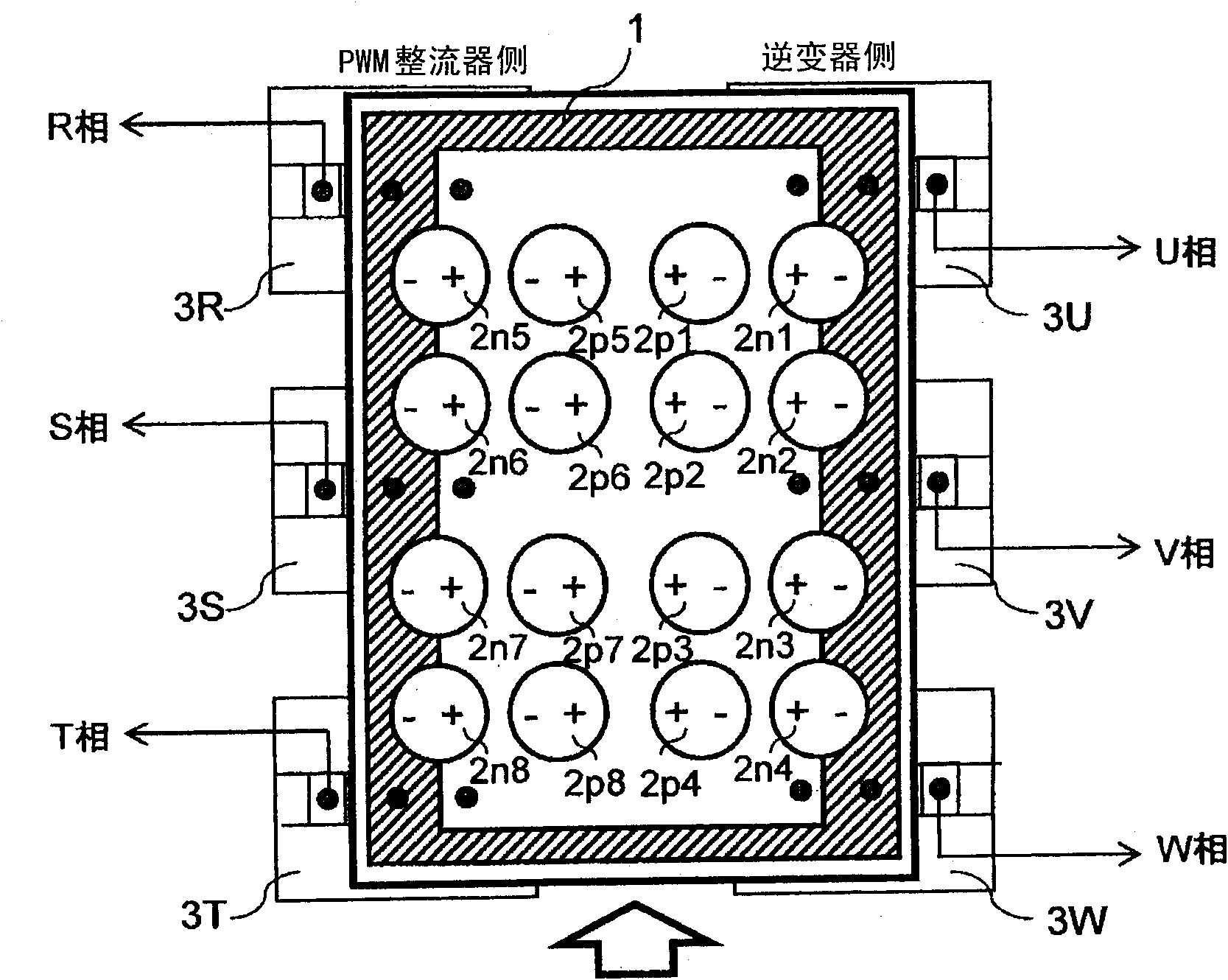
[0035] Preferred embodiments will be described below with reference to the drawings. figure 1 It is an explanatory diagram of the power conversion device according to the embodiment of the present invention. Such as figure 1 As shown, a printed wiring board (capacitor board) 1 on which capacitors are mounted includes capacitors 2p1 to 2p8, 2n1 to 2n8 mounted on the printed wiring board, switching elements 3R, 3S, and 3T on the side of the PWM rectifier, and switching elements 3R, 3S, and 3T on the side of the inverter. Switching elements 3U, 3V, 3W.

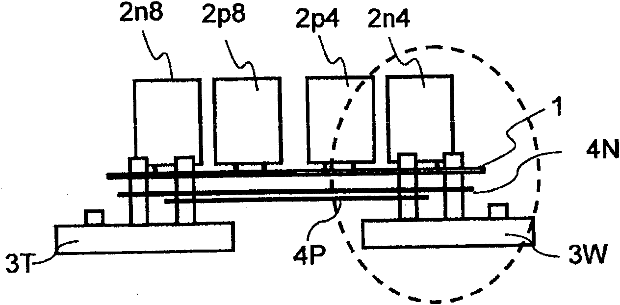
[0036] figure 2 It is viewed from the direction indicated by the arrow (A) figure 1 The side view (cross-sectional view in the direction indicated by the arrow) observed when the printed wiring board of the figure 2 As shown, a P-side wiring conductor 4P and an N-side wiring conductor 4N are provided between the printed wiring board 1 and the switching element.

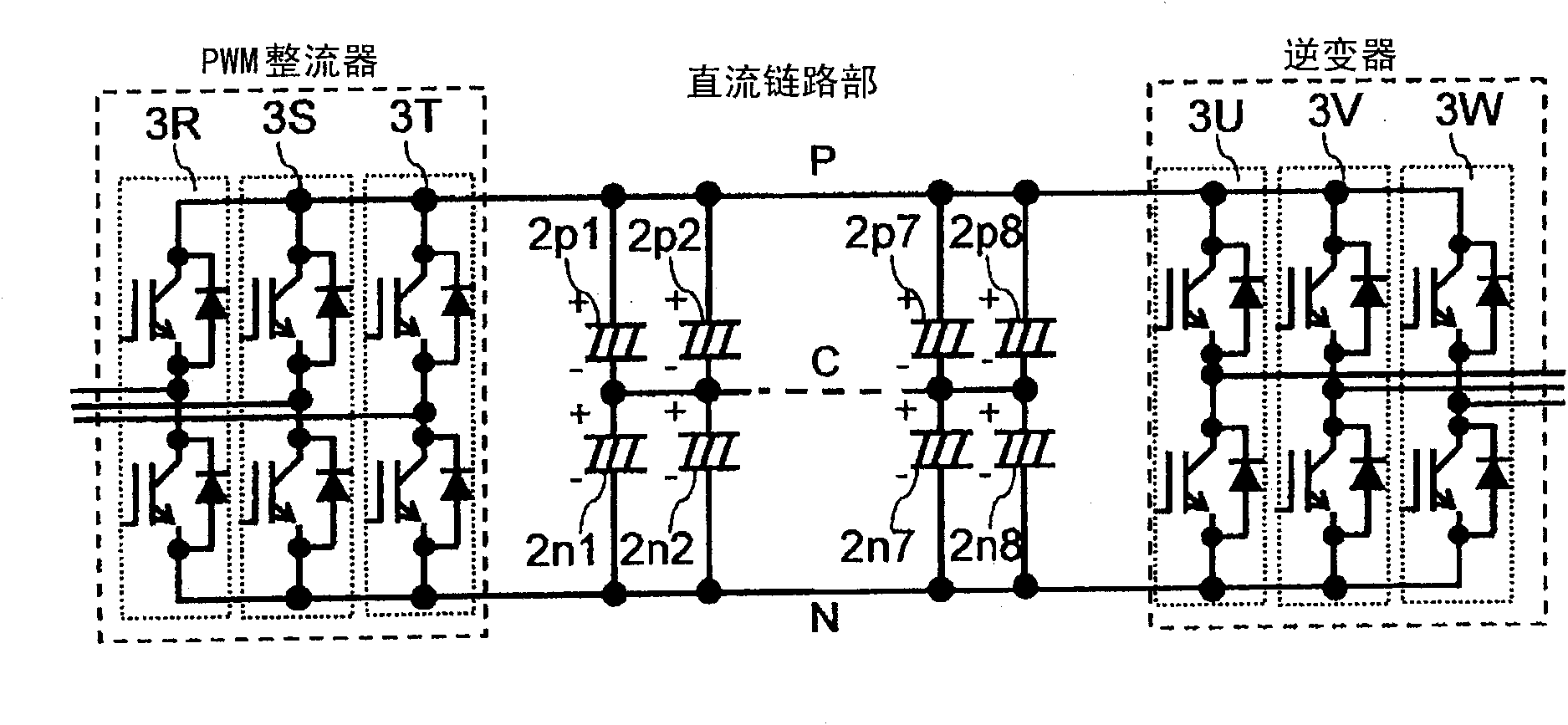
[0037] image 3 yes figure 1 In the circuit diagram of the...


PUM


Abstract

The invention provides a power converter. The insulating properties between a capacitor and the printing wiring plate pattern are improved in a power converter using a capacitor installing plate, and the low impedance of the wiring is obtained. The power converter has a DC link part for connecting a rectifying part and an inverter part, the DC link part is provided with a printing wiring plate with a smooth circuit formed by the serial connection and parallel connection of a plurality of capacitors, the printing wiring plate has negative pole patterns arranged at the upper surface side of an insulated substrate for forming a negative pole of the DC link part, positive pole patterns arranged at the lower surface side of the insulated substrate for forming a positive pole of the DC link part, and intermediate electrode patterns arranged side by side with the positive pole patterns for forming an intermediate connecting electrode of the capacitors in serial connection, wherein the negative pole patterns are formed only on a projection surface of the capacitors connected at the negative pole side of the DC link part in the capacitors in serial connection.

Description

technical field [0001] The present invention relates to a power conversion device, in particular to an installation structure of a smoothing capacitor arranged in a DC link part. Background technique [0002] In a power conversion device including a DC link unit that connects a rectification unit and an inverter unit, capacitors are provided in the DC link unit. As a mounting structure for these capacitors, for example, Patent Document 1 and Patent Document 2 are known. public scheme. Patent Document 1 and Patent Document 2 disclose methods for realizing miniaturization of the overall structure of a power conversion device. Specifically, in the servo amplifier disclosed in Patent Document 1 and the inverter device disclosed in Patent Document 2, printed circuit boards A plurality of small capacitors are arranged on a conductor plate such as the ect., thereby reducing the wiring impedance, thereby realizing the miniaturization of the overall structure of the power conversion...

Claims


Application Information

Patent Timeline
IPC IPC(8): H02M7/42
Inventor 绫野秀树大沼直人森和久迫田友治三田史明保立尚史石塚正人薮内达志
Owner HITACHI LTD
Why Eureka
Try Eureka