Handheld dehider

A peeler, hand-held technology, applied in peeling tools, slaughter accessories, portable mobile devices, etc., can solve problems such as shortening the life of parts in the tool

Inactive Publication Date: 2010-08-25
JARVIS PROD
View PDF3 Cites 8 Cited by
  • Summary
  • Abstract
  • Description
  • Claims
  • Application Information

AI Technical Summary

Problems solved by technology

Also, the wear from this motion shortens the life of the components in the tool

Method used


Image

  • Handheld dehider
  • Handheld dehider
  • Handheld dehider

Examples


Embodiment Construction

[0044] In describing the preferred embodiment of the invention, reference will be made herein to Figures 1-10 of the drawings, wherein like reference numerals indicate like features of the invention.

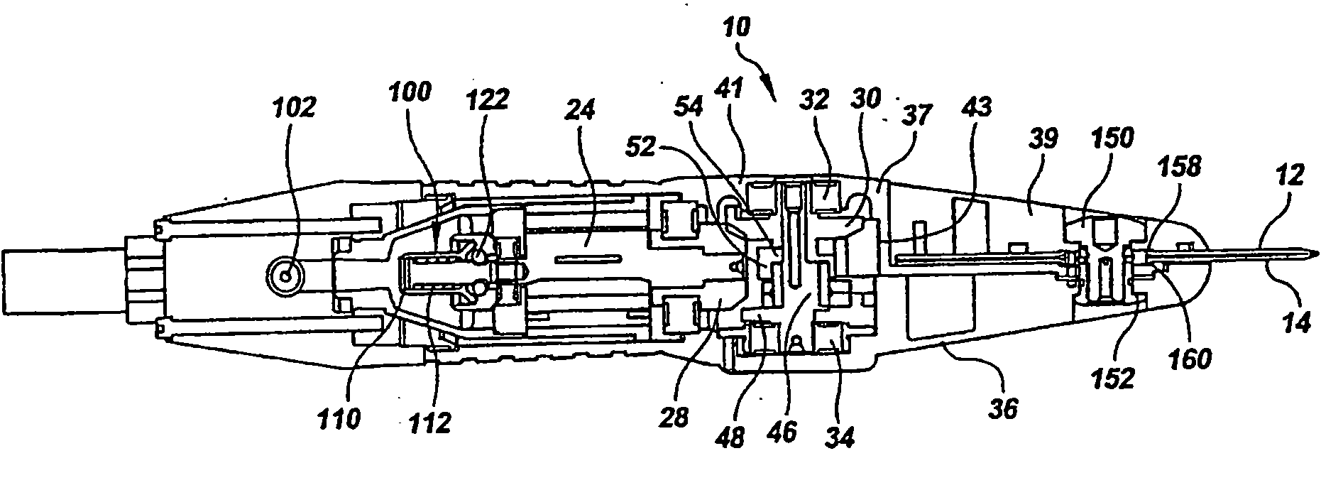
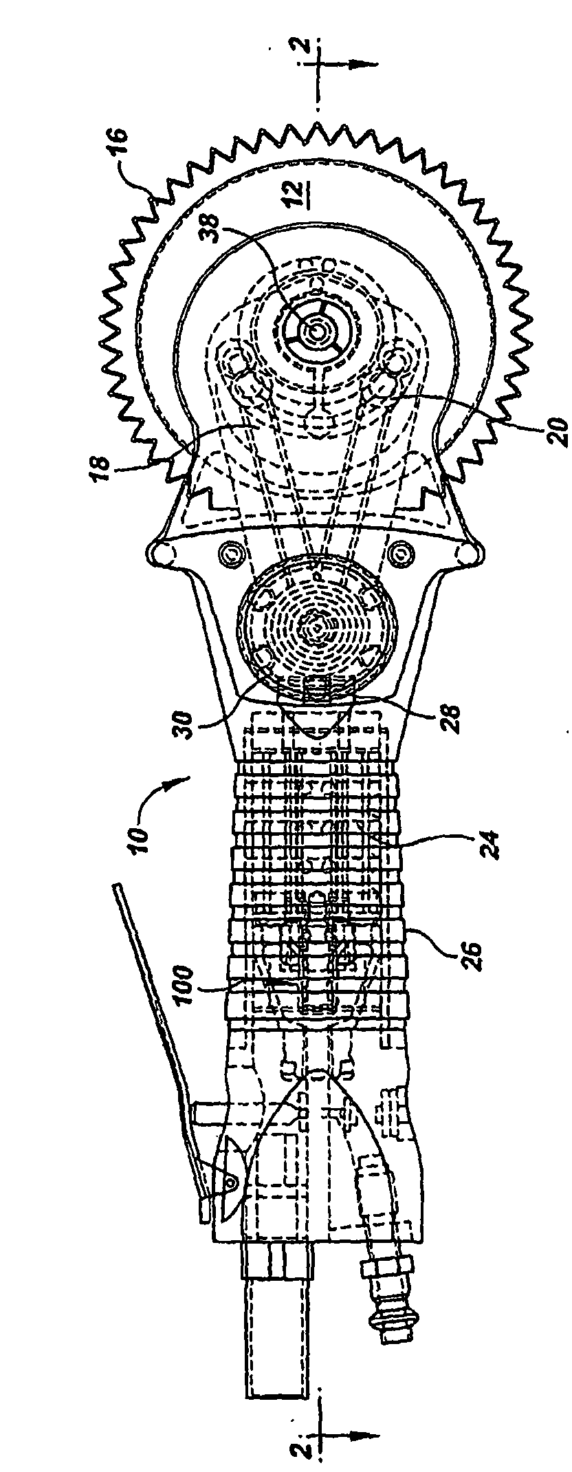
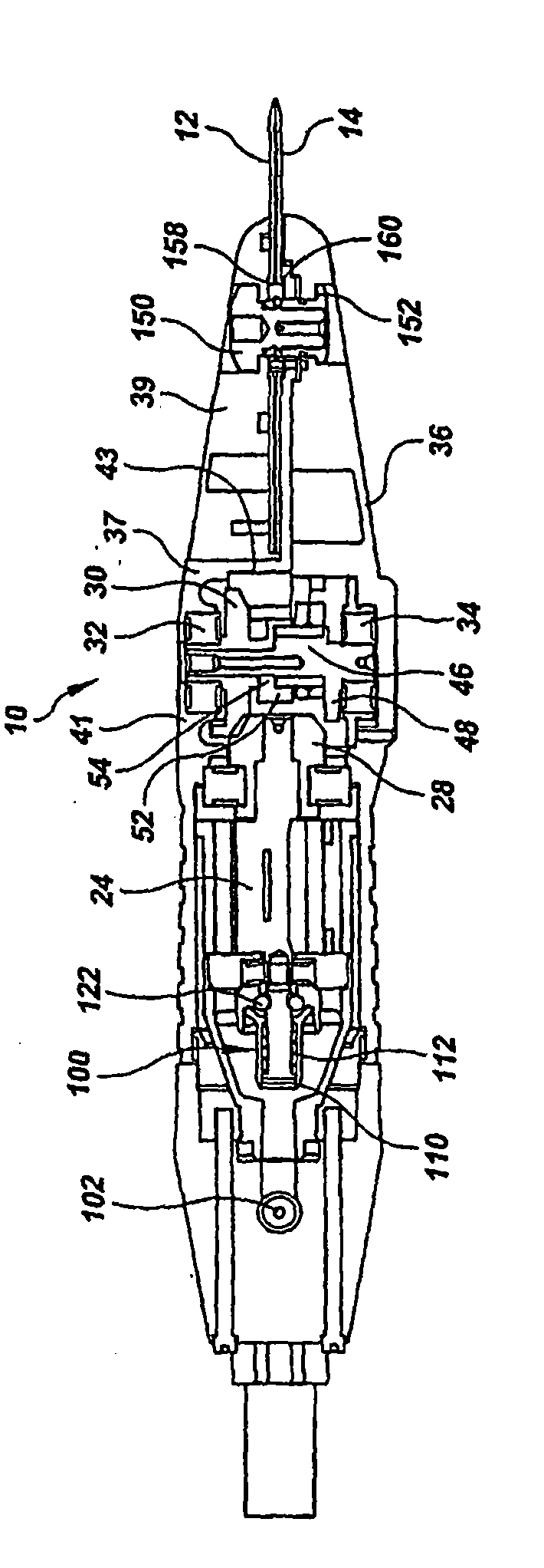
[0045] 1 and 2 show a hand-held dehider 10 according to a first embodiment of the invention. The debarker 10 includes a pair of adjacent cutting discs 12 and 14 having teeth 16 positioned around the periphery of each disc. The cutting discs 12, 14 are driven in counter-cutting oscillation by a pair of push rods 18, 20 via an eccentric shaft 22 (best seen in Figure 3).

[0046] The eccentric shaft 22 is driven by an air motor 24 located in a handle 26 of the tool housing. Motor 24 drives pinion 28 which engages and turns main drive gear 30 . The main drive gear 30 is mounted on the eccentric shaft 22 such that rotation of the motor and pinion turns the main drive gear and eccentric shaft to drive the push rod and cutting disc.

[0047] The eccentric shaft 22 is held between a ...


PUM


Abstract

A dehider (10) includes a pneumatic motor (24) driving a pair of disk blades (12) in opposed cutting oscillations and a governor that controls the speed of the motor (24). Governor balls (122), acting as centrifugal weights, spin with the motor (24) and push against an inclined flange (120) on a valve head (108) to move the valve head (108) towards a valve seat (106). The motion of the valve head(108) compresses a biasing spring (112) and restricts the flow of pressurized air as the desired speed is exceeded. As speed decreases, centrifugal force decreases and the biasing spring (112) opens the valve to provide additional power to the motor (24). The disk blades (12) are provided with a cylindrical central lip that substantially increases the area of the central bearing that the blades (12) turn on and produces significantly longer blade life.

Description

[0001] This divisional application is based on the divisional application of the Chinese patent application whose application number is 200680034168.8, the application date is September 14, 2006, and the invention name is "hand-held peeler". technical field [0002] The present invention relates to hand-held skinners and power skinners for removing the skin from carcasses in meat processing facilities. More specifically, the present invention relates to debarkers using a pair of cutting discs driven in counter-cutting oscillating fashion. Background technique [0003] Hand-held skinners are used in meat processing equipment to facilitate the removal of skin from animal carcasses. The most common type of debarker consists of a pair of adjacent cutting discs or blades driven in counter-cutting oscillating motion by a corresponding pair of push rods. This basic design is shown in US Patent No. 5,122,092 assigned to Jarvis Products Corporation (ie, the assignee of the present i...

Claims


Application Information

Patent Timeline
Patent Type & Authority Applications(China)
IPC IPC(8): A22B5/16
CPCA22B5/168A22B5/163B25F5/00B25F5/006B26B25/00
Inventor P·格威瑟
Owner JARVIS PROD
Why Eureka
Try Eureka