Low-temperature trace lubrication system

A micro-lubrication, low-temperature technology, used in metal processing machinery parts, maintenance and safety accessories, metal processing equipment, etc., to achieve the effect of less consumables, low cost, and less consumption of resources

Inactive Publication Date: 2010-08-25
BEIHANG UNIV
View PDF7 Cites 39 Cited by
  • Summary
  • Abstract
  • Description
  • Claims
  • Application Information

AI Technical Summary

Problems solved by technology

[0004] The purpose of the present invention is to propose a low-temperature micro-quantity lubrication system

Method used


Image

  • Low-temperature trace lubrication system
  • Low-temperature trace lubrication system
  • Low-temperature trace lubrication system

Examples


Embodiment 1

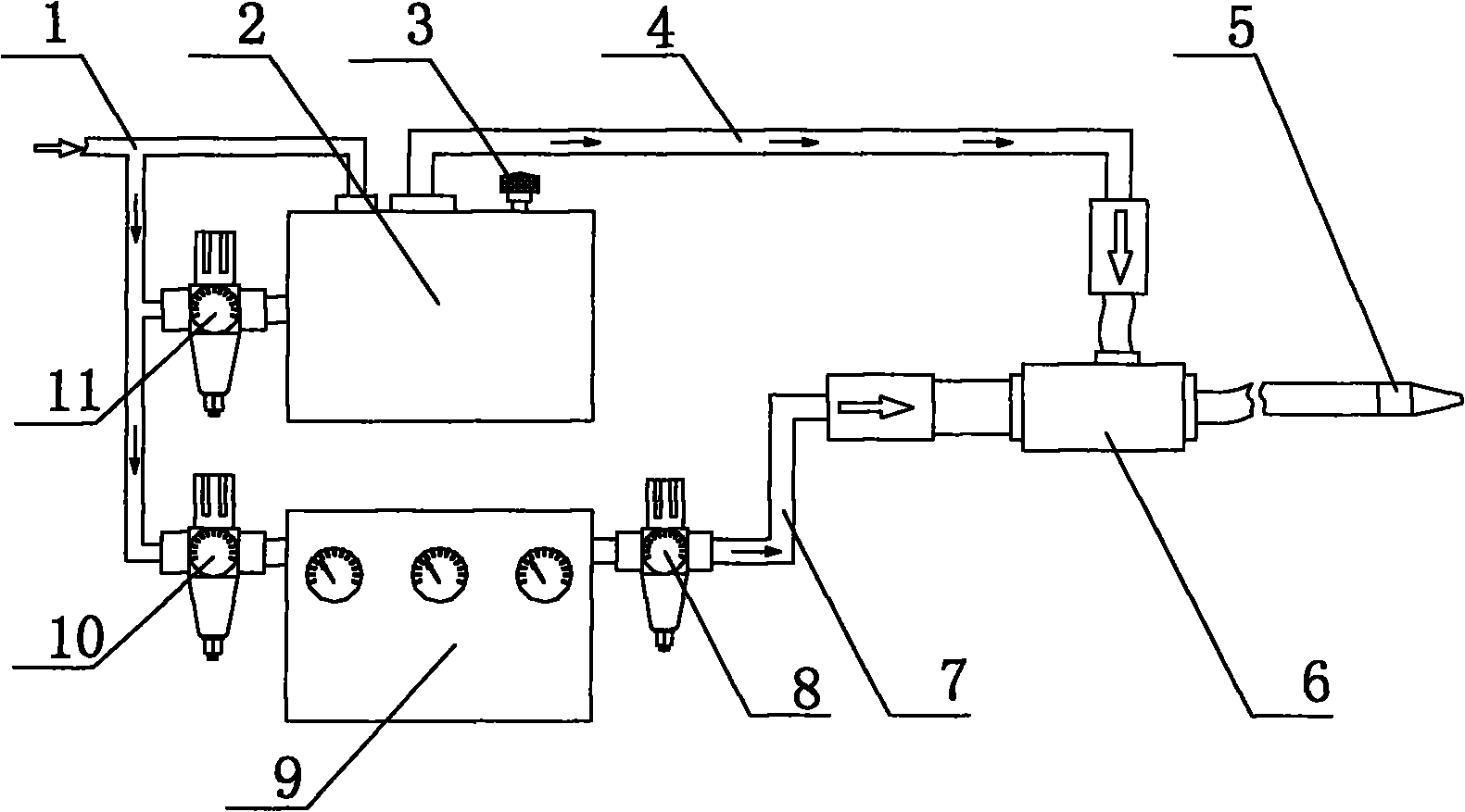
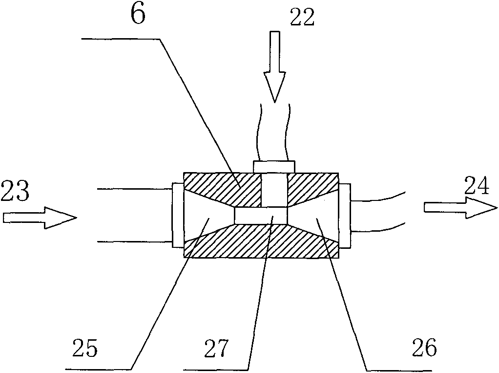
[0042] See Figure 1-3 , the present invention proposes a low-temperature micro-lubrication system, which is specifically composed of an air source pipeline 1, a micro-quantity lubrication device 2, an oil quantity regulating valve 3, an oil mist pipeline 4, a nozzle 5, a mixer 6, a cold air pipeline 7, a low-temperature The gas flow regulating valve 8, the low-temperature gas generating device 9, the low-temperature gas generating device pressure-regulating valve 10, and the micro-quantity lubrication device pressure-regulating valve 11 are composed.

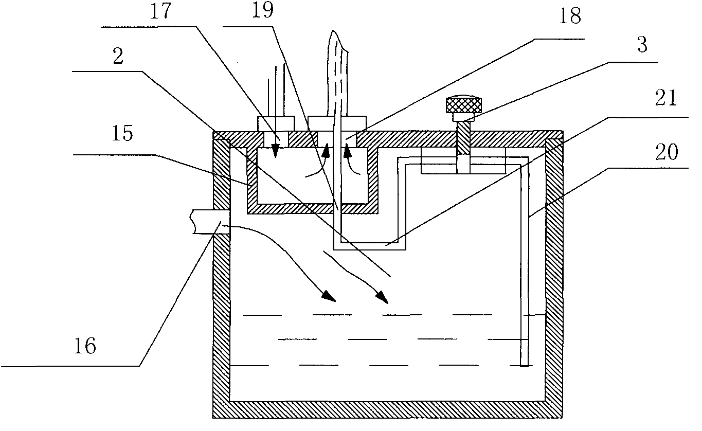
[0043] The micro-quantity lubrication device 2 specifically includes an oil tank 14, an air cavity 15, a gas inlet 16 of the oil tank, a gas inlet 17, a gas outlet 18, an oil outlet 19, a liquid introduction pipe 20, a connecting pipe 21, an oil quantity regulating valve 3 and a micro-quantity lubrication device Pressure regulating valve 11, etc.,

[0044] The air cavity 15 is arranged on the top of the inside of the fuel tank...

Embodiment 2

[0056] See Figure 4 , another embodiment of a low-temperature micro-quantity lubrication system of the present invention, which is specifically composed of an air source pipeline 1, a micro-quantity lubrication device 2, an oil quantity regulating valve 3, an oil mist pipeline 4, an oil mist nozzle 12, a cold air nozzle 13, a cooling Gas pipeline 7, low-temperature gas flow regulating valve 8, low-temperature gas generating device 9, low-temperature gas generating device pressure regulating valve 10, and micro-quantity lubrication device pressure regulating valve 11.

[0057] The difference from the previous embodiment is that in this low-temperature minimal quantity lubrication system, the oil mist pipeline 4 and the cold air pipeline 7 are not connected to a mixer, but the end of the oil mist pipeline 4 is directly connected to an oil mist nozzle 12 , the cold air pipeline 7 is directly connected with a cold air nozzle 13 . Wherein the oil mist nozzle 12 is an inner and ou...


PUM


Abstract

The invention relates to a low-temperature trace lubrication system which is characterized in that the system comprises a gas source pipeline, a trace lubrication device, an oil mass regulating valve, an oil mist pipeline, spray nozzles, a mixer, a cold gas pipeline, a low-temperature gas flow regulating valve, a low-temperature gas generation device, a pressure regulating valve of the low-temperature gas generation device and a pressure regulating valve of the trace lubrication device. Part of compressed gas enters the trace lubrication device by the gas source pipeline, and the other part of the compressed gas enters the pressure regulating valve of the low-temperature gas generation device and the pressure regulating valve of the trace lubrication device. After the pressure of the compressed gas is regulated by the pressure regulating valve of the trace lubrication device, the compressed gas enters the trace lubrication device, and a generated oil-gas mixture enters the oil mist pipeline. After the pressure of the compressed gas is regulated by the pressure regulating valve of the low-temperature gas generation device, the compressed gas enters the low-temperature gas generation device, and generated cold gas enters the cold gas pipeline after the flow of the cold gas is regulated. The mixing mode of oil mist and cold air can be mixer mixing and can also be mixing after being ejected by the respective spray nozzles.

Description

(1) Technical field: [0001] The invention relates to a low-temperature micro-lubrication system, in particular to a low-temperature micro-lubrication system which atomizes a lubricant and mixes it with cold air and sprays it to a cutting area at high speed to realize cooling and lubrication. The utility model relates to a liquid supply device belonging to the field of mechanical processing. (two) background technology: [0002] Extensive use of cutting fluid has become an important source of pollution to the environment in the field of mechanical processing, and has caused various negative effects: waste cutting fluid is an important source of pollution of soil and air, and cutting fluid mist can easily cause various diseases after being inhaled by workers; The cost of purchase, storage, and post-processing is high. Corrosive cutting fluid will change the color of the workpiece and corrode the gasket; traditional cutting fluid has a thermal shock effect on the surface of som...

Claims


Application Information

Patent Timeline
IPC IPC(8): B23Q11/10
Inventor 袁松梅严鲁涛刘伟东刘强
Owner BEIHANG UNIV
Why Eureka
Try Eureka