Composite metal plastic pipe extrusion molding device and molding method thereof

A steel-plastic composite pipe and extrusion molding technology, applied in the field of polymer material molding and processing equipment, can solve the problems of limiting extrusion speed, increasing energy consumption, and large resistance of extrusion melt, eliminating mold expansion, reducing The effect of material waste and improved product accuracy

Inactive Publication Date: 2010-08-25
DALIAN MARITIME UNIVERSITY
View PDF3 Cites 8 Cited by
  • Summary
  • Abstract
  • Description
  • Claims
  • Application Information

AI Technical Summary

Problems solved by technology

[0003] 1. Extrusion swelling is easy to occur: extrusion swelling increases the difficulty of extrusion die design and affects the accuracy of composite pipes
[0004] 2. The pressure drop in the flow channel of the extrusion die is large: the internal stress of the extruded composite pipe increases, resulting in increased deformation and increased energy consumption
[0005] 3. Surface defects of the extruded product: Because the extrusion speed exceeds the critical extrusion speed of the material, the phenomenon of "turtle skin" and extrusion cracking on the surface of the product, the appearance of surface quality defects of the extruded product limits the extrusion speed. Improve, affect production efficiency
[0006] The above three major problems seriously affect the precision of composite pipe products, limit the increase in extrusion speed, and lead to high energy consumption for extrusion
The root of the above problems is that the traditional extrusion technology adopts the non-slip adhesion shear die extrusion method, which makes the resistance of the die wall to the extruded melt large.

Method used


Image

  • Composite metal plastic pipe extrusion molding device and molding method thereof
  • Composite metal plastic pipe extrusion molding device and molding method thereof
  • Composite metal plastic pipe extrusion molding device and molding method thereof

Examples


Embodiment Construction

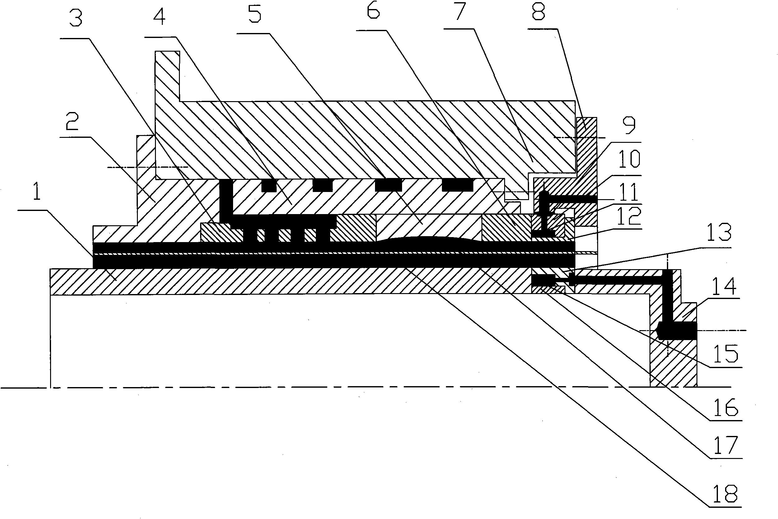
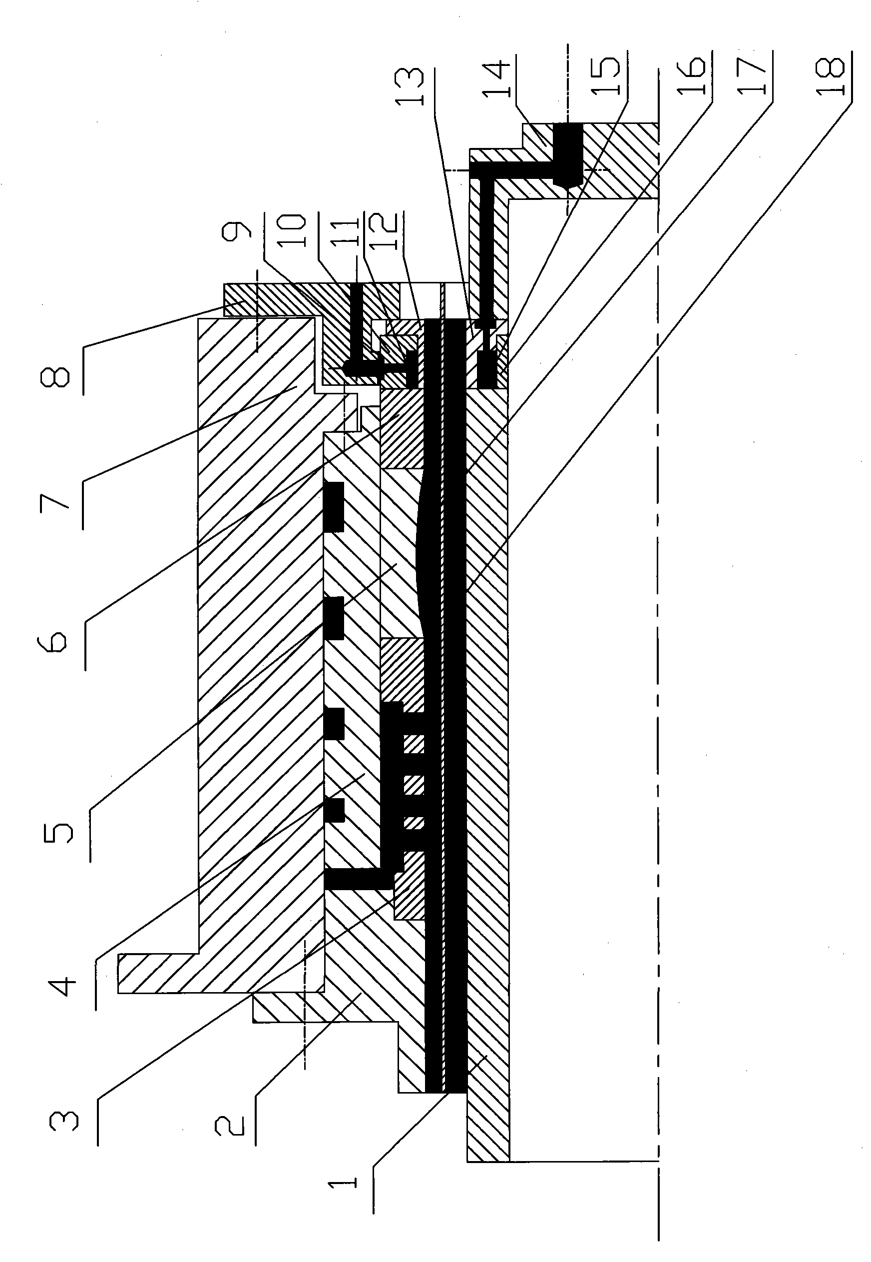
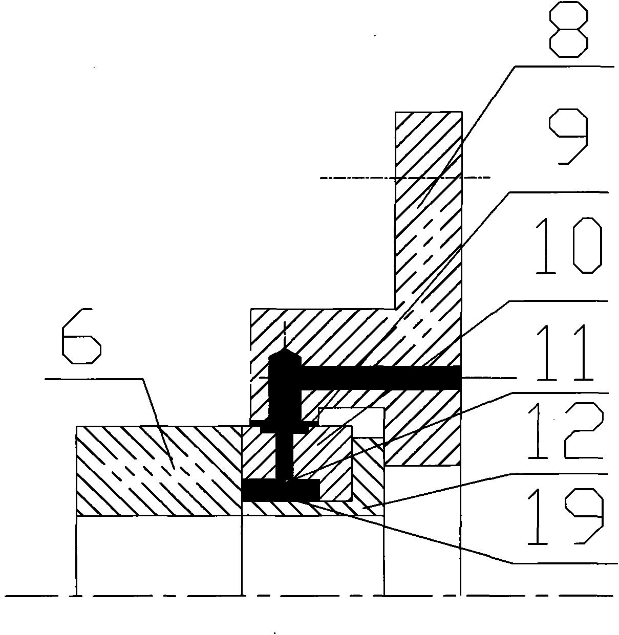
[0027] The present invention will be further described below in conjunction with the accompanying drawings. As shown in Figure 1-3, a steel-plastic composite pipe extrusion molding device includes a screen hole sleeve 3, a connecting flange 2, a compression sleeve 5, a mandrel 1, a uniform material sleeve 4, an airless auxiliary die 6 and Connect the jacket 7, the right end of the air-assisted die 6 is connected with the gas-assisted die 12, the gas-assisted die coat 10 is installed on the outside of the gas-assisted die 12, and the air-assisted die coat 10 is connected with the air-assisted die coat 12. The die inlet cover plate 8 is connected, and the airtightness of the gas passage is ensured by the sealing ring 9; the right end of the mandrel 1 is connected with the gas-assisted mandrel 13, and the inner side of the gas-assisted mandrel 13 is installed with a mandrel inner Cover 16, the right end are connected with mandrel air inlet cover plate 14. The air-assisted die 6,...


PUM


Abstract

The invention discloses a composite metal plastic pipe extrusion molding device and a molding method thereof. The device comprises a sieve mesh cover, a connection flange, a wedging ring, a core rod, a material cover, an airless assisted mold and a connecting outer cover; the right end of the airless assisted mold is connected with an air assisted mold; the outer side of the air assisted mold is provided with an air assisted mold outer cover; the air assisted mold outer cover is connected with a mold air inlet cover plate; the leak tightness of air passage is guaranteed through a sealing ring; the right end of the core rod is connected with the inner cover of the core rod; and the right end is connected with the air inlet cover plate of the core rod. The method comprises that lubrication gas with certain pressure is divided into two paths while entering the air assisted molding passage. Since stable air cushion films are formed between the mold, the core rod and the plastic melt, thereby reducing the extrusion pressure, saving the energy consumption, basically eliminating die swelling, improving precision of products, reducing material waste, shortening molding period, and saving the cost.

Description

technical field [0001] The invention relates to a polymer material forming processing equipment, in particular to a steel-plastic composite pipe extrusion forming device and a forming method thereof. Background technique [0002] Steel-plastic composite pipe is a kind of double-sided anti-corrosion pipe with excellent performance, which is continuously formed on the extrusion production line with steel wire mesh or steel plate as the reinforcement phase and high-density polyethylene and polypropylene as the matrix. Its remarkable structural feature is the integration of the corrosion resistance of plastics and the high strength of steel pipes, and has been widely used in petroleum, natural gas, chemical, municipal and other fields. The existing steel-plastic composite pipe extrusion molding device mainly includes a screen hole sleeve, a connecting flange, a compression sleeve, a mandrel, a material equalizing sleeve, a die and a connecting sleeve, but due to the high viscosi...

Claims


Application Information

Patent Timeline
Patent Type & Authority Applications(China)
IPC IPC(8): B29C47/00B29C47/20B29C48/32
Inventor 马文琦熊伟王海涛弓永军关广丰张增猛
Owner DALIAN MARITIME UNIVERSITY
Why Eureka
Try Eureka