Combined bit

A composite drill bit and cutter head technology, applied in drill bits, drilling equipment, earthwork drilling and other directions, can solve problems such as affecting the construction quality of underground diaphragm walls, unstable drilling quality, blade wear and tear, etc.

Inactive Publication Date: 2010-08-25
上海工程机械厂有限公司
View PDF7 Cites 12 Cited by
  • Summary
  • Abstract
  • Description
  • Claims
  • Application Information

AI Technical Summary

Problems solved by technology

[0003] In the prior art, the drill bit of the multi-spindle drilling rig generally adopts the drill tool and drill bit of the improved long helical drilling rig, such as a new type of drilling tool, the patent number is ZL200720070011.2, which is fixed on the drill rod by two helical blades The front end, three rows of cutter bodies are arranged crosswise and fixed on the bottom edge of two helical blades, and the head of the cutter body is surfacing with tungsten carbide. Quality problems such as serious wear of the cutting edge, shedding of the cutter head, and wear and tear of the blades not only affect the construction efficiency of the drilling operation, but also make the drilling quality unstable, directly affecting the construction quality of the underground diaphragm wall

Method used


Image

  • Combined bit
  • Combined bit
  • Combined bit

Examples


Embodiment Construction

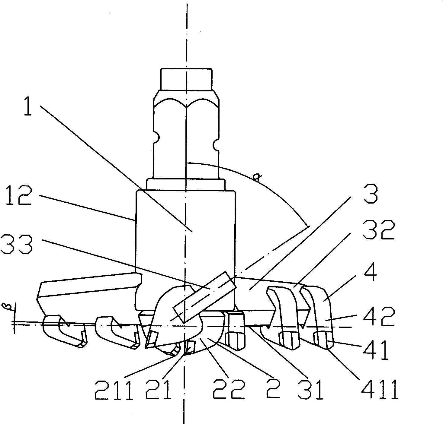
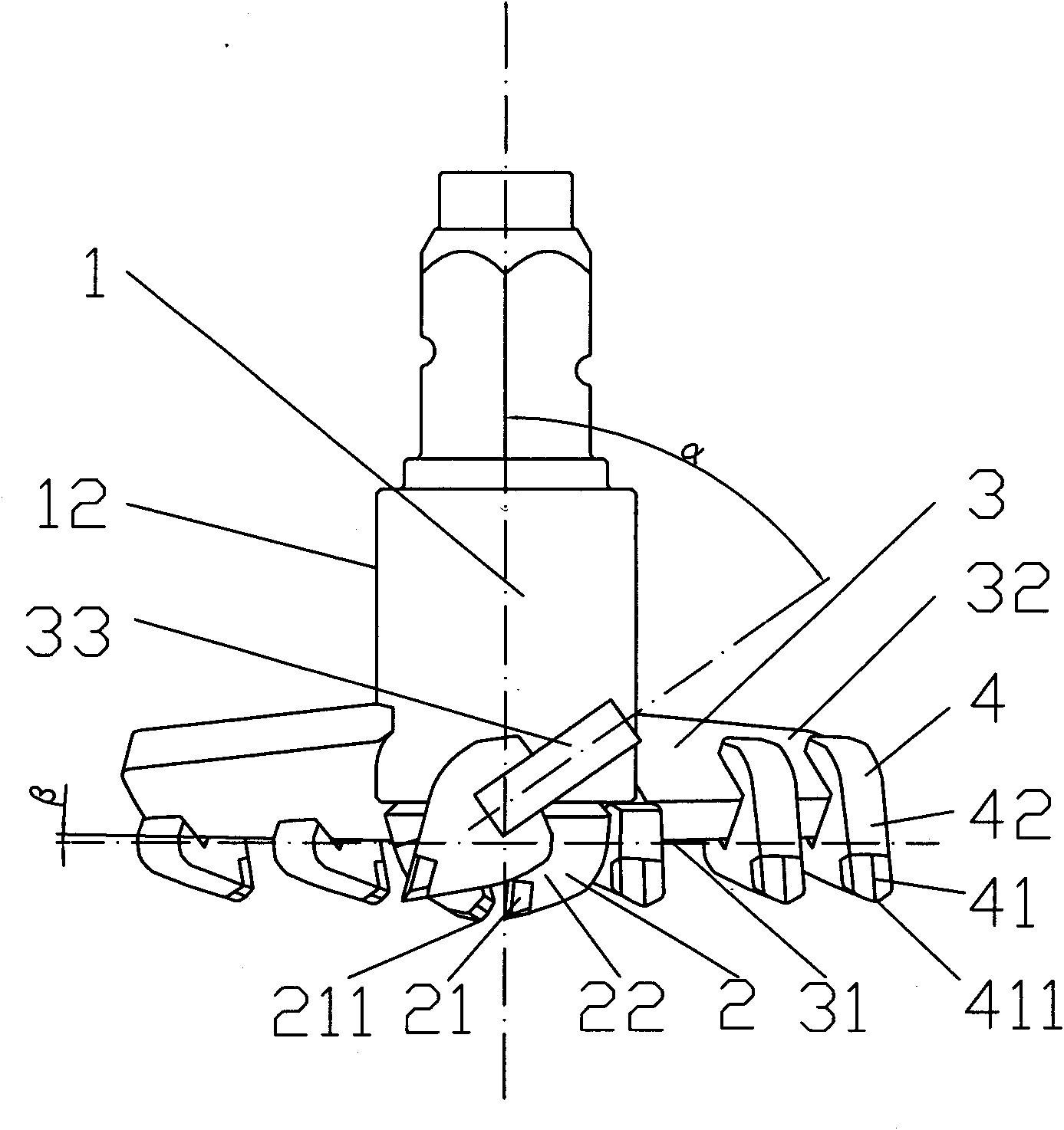
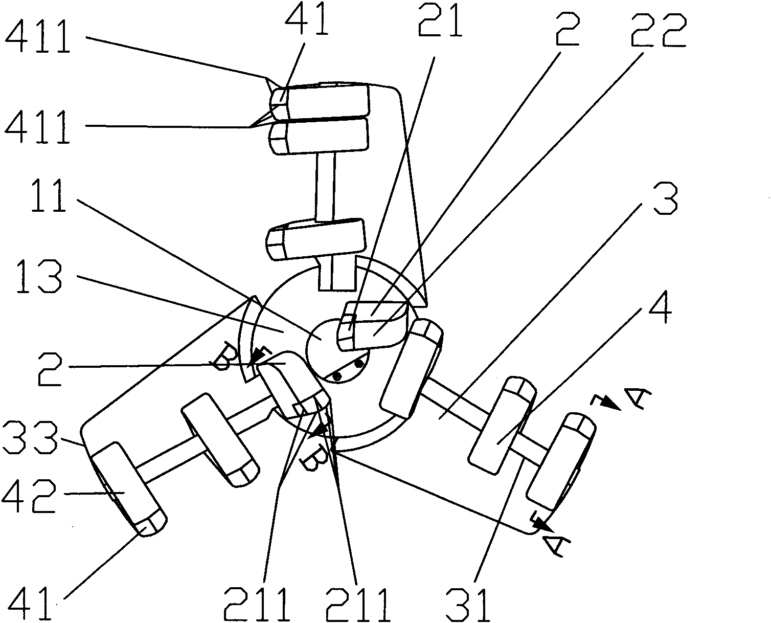
[0019] As shown in Fig. 1, Fig. 2, Fig. 3 and Fig. 4, a kind of compound drill bit, comprises rod body 1, the inner cutter body 2 that is made up of inner cutter head 21 and inner cutter handle 22, fin 3, consists of outer cutter head 41 and An outer cutter body 4 composed of an outer cutter handle 42; wherein, a grouting channel 11 is provided in the middle of the rod body 1 for pouring cement slurry; an inner cutter body 2 is fixed on the lower end of the rod body 1, and there are 2-4 inner cutter bodies 2, The lower end of the rod body 1 is provided with a flange 13, and the inner cutter body 2 is fixed on the lower surface of the flange 11 of the rod body 1 by radially symmetrical welding of the inner knife handle 22; The axial centerline direction of the rod body 1 is uniformly fixed on the outer peripheral surface of the rod body 1 bottom, and the outer cutter body 4 is fixed on the fins 3; The included angle α=50-70° of the axial center line; the included angle β=0-15° ...


PUM


Abstract

The invention relates to a combined bit, comprising a rod body, an inner cutter body consisting of an inner cutter head and an inner cutter handle, wings and an outer cutter body consisting of an outer cutter body and an outer cutter handle, wherein the middle part of the rod body is provided with a grouting channel, and the inner cutter body is fixed at the lower end part of the rod body; the number of the wings is 2-6 and are uniformly distributed and fixed on the peripheral surface of the lower part of the rod body along the length direction thereof vertical to the direction of an axial central line of the rod body, and the outer cutter body is fixed on the wings; the inner cutter head in the inner cutter body and the outer cutter head in the outer cutter body are respectively welded the inner cutter handle with the outer cutter handle into a whole; the front ends of the inner cutter head and the outer cutter head are respectively provided with an inner cutting edge and an outer cutting edge; and the installation directions of the inner cutter body and the outer cutter body are rotating directions leading the inner cutter head and the outer cutter head to be installed toward the rod body. The combined bit realizes synchronous drilling and cutting of the inner cutter head and the outer cutter head, improves the operating efficiency multiply, has high bonding strength of the cutter heads and the cutter handles, reduces the wear condition of the cutter heads and the wings, and guarantees the quality of continuous walls after drilling holes.

Description

technical field [0001] The invention relates to a composite drill bit capable of penetrating strata, especially sandy soil strata, which can be widely used in underground deep foundation projects such as underground facilities of high-rise buildings, foundation pit enclosure of subway stations, reinforcement of river dams and improvement of soft soil foundations, etc. need. Background technique [0002] In the construction process of underground foundation projects such as urban high-rise buildings, deep foundation pit enclosure of subway stations, anti-seepage reinforcement of river dykes and soft soil foundation improvement and reinforcement, a large number of SMW construction method equipment is currently used to construct underground diaphragm walls, that is, multi-axis drilling rigs are used. The technology of continuously drilling, mixing soil and cement slurry in situ and inserting section steel to build underground retaining and waterproof walls, which plays the role...

Claims


Application Information

Patent Timeline
Patent Type & Authority Applications(China)
IPC IPC(8): E21B10/43E21B10/54
Inventor 龚秀刚张国柱朱亚萍黄敏
Owner 上海工程机械厂有限公司
Why Eureka
Try Eureka